Start of…
This is a slightly updated version of my previous tutorial (from twenty years ago), which can still be found at: http://oldies.malban.de/secondvectrex/toc.htm
Introduction
This document is supposed
to give people a start in Vectrex programming. For my sake I will assume that
you are familiar with non ‘Vectrex special’ related hardware and software used.
Such as programming a 6809 cpu in assembler, what hex, bin and dec numbers are,
what a 256 byte page is and so on. I will try to cover many aspects, but mainly
will cover ‘standard’ procedures offered by the Vectrex BIOS.
(for starters you might look at Christopher L. Tumbers document: TUTORIAL.TXT)
This was started in April 1998 by Malban the document is public domain (at least the parts written by me). Comments and Vectrex talk are welcome.
All code within this document was successfully assembled using Vide. The widely used Assembler AS09 from ‘Frank A. Vorstenbosch, Kingswood Software’ Crossassembler should also assemble all examples. It can be found at his homepage at http://www.kingswood-consulting.co.uk/assemblers/.
(Note: via command line
option the AS09 can be told to ignore case)
Following command line was used to assemble:
as09.exe
-w200 -h0 -l -mcti progname.asm >error
Conventions
Functions we will use are named like Print_Str_d ($F37A). The hex number is the ROM address of the function. Most of the time the function name also gives a hint as to which registers are used in passing information. The above function uses the D register to pass position information (A=ypos, B=Xpos, with D=A*256+B).
This convention has its origin with the disassembly of the Vectrex ROM done by Bruce Tomlin. I started to learn Vectrex from that source.
Later the official Development documents became openly available, but by then I was so used to Bruce Tomlins names, that I never converted back to the “original” names. Also – IMHO – the original names are a lot less descriptive, and I find it ways easier (in most cases) to remember and use the names given by Bruce.
Examples in this tutorial
Since I am the programmer
of Vide (Vectrex integrated development environment) I use mainly Vide for my own
Vectrex development needs.
All examples given in this tutorial are runnable in Vide. Additionally, since
my own Vectrex programming career started off with a different assembler, all
programs should also be able to assemble with the “Kingswood”
assembler (there is “-i” command line switch to ignore cases of
mnemonics!).
General assembler guidelines
If you start assembler programming you have to learn much stuff. I beg of you please also learn the following couple of assembler directives. It might seem in the beginning unnecessarily complicated. But I assure you – in the long run it leads to better structured code which is also better maintainable.
Segments
This code lies from memory position 0 to 0x7fff.
Since our programs in general need also some variables (positions where our player is headed, score counter, level counter etc.) we need additionally some memory that can be changed. This memory goes under the headline “RAM” (Random access memory).
A Vectrex has 1024 bytes of RAM, located 0xc800 – 0xcbff.
The assembler needs to know where our RAM and ROM locations are based (the assembler can also be used to program other machines, where the memory layout might be different).
Why does the assembler need to know?
Because it only needs to create code (assembled instructions…) for ROM locations. RAM locations are at the time of assembling NOT filled with any values. You as a programmer must fill RAM locations with default values. The only interesting thing for the assembler is WHERE the RAM is located not what the RAM is filled with.
There are two special assembler directives (which are interesting for Vectrex programmers) these are “bss” and “code” (see below).
For each segment you have to tell the assembler its memory base address (using the special assembler instruction: “org”).
Switching between segments (if you wish) also switches between the memory addresses of these segments.
You can write Vectrex programs without using the “code” and “bss” pseudo opcodes, but together with some other pseudo opcodes you can program “cleaner” and better structured / documented programs.
Pseudo Opcodes used
What is “bss”?
(Block Started by Symbol)
The pseudo opcode “bss” tells the assembler that a (uninitialized) RAM section is about to start. Per default the start address of all segments is at address 0x0000. Since the Vectrex (usable) RAM starts at address 0xc880 the “bss” pseudo opcode is usually followed directly by a “org 0xc880” (or similar).
What is “code”?
The pseudo opcode “code” tells the assembler that the ROM section is about to start. Per default the start address of all segments is at address 0x0000. Since the Vectrex ROM starts at address 0x0000 the “code” pseudo opcode is usually followed directly by a “org 0x0000” (or omitted, since that is the default).
What is “org”?
Forces the assembler to set the current memory address to a certain value. The memory address is set for the current active segment.
What is “include”?
With “include” you load other files “into” your current source file. The “include” statement is actually replaced with the contents of the file it denotes. The resulting file is treated as if it was one file to begin with. Using include statements (e.g. to define constants, variables and macro definitions) can lead to much more readable code and enables you to easily reuse sections of your code.
What is “direct”?
Tells the assembler what it should use as the current direct page address (for the Vectrex it most often is either $d0 [IO for VIA] or $c8 [base address for BIOS-RAM]).
The programmer still must ensure that the DP register of is also set to the correct value!
What is “macro”?
Together with “endm” defines a macro.
What is “struct”?
Together with “end struct” defines a struct.
What is “EQU” or “=”?
Defines constants.
What is “if”?
Together with “else” and “elseif” and “endif” defines conditionals for the assembler.
What
is ds, db, dw, fcb, fdb?
db semantically equals fcb (form constant byte) or fcc (form constant
character)
dw semantically equals fdb (form double byte)
ds semantically equals rmb (reserve memory block)
db – insert initialized
“data” statements of byte value (ascii) (only sensible in code
segment)
dw – insert initialized “data” statements of word value (only
sensible in code segment)
ds – reserve a number of uninitialized bytes (mostly used in bss segments)
Note on bss and ds:
You can circumvent the use of these two pseudo opcodes.
You do not have to define any (RAM) memory locations in program at all. You can do all RAM addressing using definitions of constants, like:
 coll_00 equ $C880
 coll_01 equ $C885
And then treat e.g. “col1_00” as a 5 byte allocation area for e.g. a collision detection (and so forth).
But you will see (after some programming and changes you might do) that doing instead something like:
 bss
 org $c880
 coll_00 ds 5
 coll_01 ds 5
(which semantically is exactly the same)
Is a much better way to organize your program.
One can easily change locations, add length to your reservations etc. without changing whole platoons of variables. Also if you decide to use RAM locations more than once you can also easily do another:
 bss
 org $c880
 Ship1_00 ds 5
 Ship2_01 ds 5
And fill your RAM definitions with a new set of variables.
Vectrex – something different?
Programming the Vectrex is a bit different than programming other systems. Depending on where your programming origins lie – quite a lot different.
There might be a couple of major differences to your prior experiences.
1) Vectrex is a machine from the earlier “computer/video game” era
2) Vectrex is a gaming console, not a computer
3) Vectrex is a vector machine (not a raster machine)
Early era
Since quite some time now (if I were to guess, I’d say starting with the Super NES, or later DOS days (earlier Windows days)) programming “machines” is usually done
- using high level languages
- using libraries and APIs
The Vectrex actually is “in between”. While no original program (that I know of) has been programmed using a high level language, the BIOS (Basic Input Output System) of the Vectrex features many routines that are solely intended to be used by game programmers – in this regard the Vectrex is similar to the Colecovision – it has a usable BIOS. Unlike (VCS 2600 or NES or some other gaming system).
This means you can start your Vectrex programming career using the BIOS library. Which makes the learning curve much more shallow and the whole experience much more enjoyable. Since it means you can basically write a hello world program in a couple of lines – and actually also understand it!
Good – there is a usable BIOS!
Not so good – (for beginners) you should use Assembler.
(Note: Vide also supports programming the Vectrex using “C”. There a several cartridges that support other languages, like LOGO or BASIC and perhaps in the future even FORTH.)
Console vs Computer
In “current” programming languages and programming systems the programmer doesn’t really have to think about how the memory of the machine is organized. With object oriented language you most often have garbage collection and do not waste a thought about memory in any direction. In more “classic” languages (“C”?) you “reserve” the memory through library calls and use it and free it. But you virtually NEVER organize your own memory.
With the Vectrex you have to organize the memory of your own.
Furthermore – you have to know and respect that there are different memory areas. You must know what their purpose is and how to take advantage of that.
There are several types of memory locations:
1) Cartridge ROM
here your “own” program will finally be located
2) unused memory
memory locations in the 64kB range that you cannot use
3) IO locations
“special” memory locations that are used to communicate with peripherals
4) RAM
the Vectrex has only 1024bytes of RAM
5) “factory” ROM
the ROM space every Vectrex has in common, that is never changed by the user in any way (Minestorm – and the BIOS)
Vector machine
Nowadays virtually all graphic outputting devices are raster based (yes, CRT, Plasma, LCD, OLED displays – all are raster based). A possible very simplistic explanation would be something like:
One writes directly to the screen, and the screen remembers what you wrote and keeps displaying it, till you change it
(Yes, very simplistic…)
Why is it called “raster” display? Because you have a fixed screen resolution, something like 1024×768. Everything you display must be placed on a “x”position that is an integer value between 0 – 1023 and at a “y”position from 0 – 768.
You can think of each coordinate as a tiny rectangle that is either lit or not lit (or has color). Altogether you can light up to 1024*768 little rectangles (pixels) – that is 786432 locations. So the screen consists of thousands of dots that are either lit or not lit (colored). Depending on your monitor and your graphics capabilities you can change the dot at fixed rates (50Hz, 60Hz, 100Hz). The higher the frequency the smoother the display.
Go back some 20-30 years. Before OLED, before LCD, before PLASMA – there were only CRTs (Cathod Ray Tubes). That was a time when a monitor was sometimes deeper than wide (especially color monitors).
While CRT’s are (mostly) also raster based, they did not have crystals or
LEDs that illuminated the screen they instead had (as the name suggests) a
“ray”. In principle the (electron) ray (or three rays for color monitors)
illuminated a phosphor coated vacuum tube. A monitor at that time, when it had
50Hz, had the ability (let’s say again its resolution was the same as above
1024×768) to move the electron ray (again very simply put) 768 times from left
to right and in between move a tiny step down. In one such a line it could
switch the electrons on and off up to 1024 times.
If such a monitor had 50Hz it could do a “whole” screen update 50
times a second – hence 50Hz.
If the electron ray was switched off – the screen was black at that spot. 50Hz
for normal human eyes is right on the boarder of being “flickery”.
In the dark ages of video games – all monitors were television sets. Depending if you lived in Europe or America (or whatever other place on earth) your television sets used 50Hz (Europe PAL) or 60Hz (NTSC) with different resolution (Europa higher resolution, America lower resolution).
Anyway, the resolution and frequency for any given raster screen (mode) is FIXED. The electron beam can only move in predetermined paths at a predetermined speed and can only be switched on and off at predetermined “integer values” – within the RASTER.
Not so with a vector display. As a programmer of a vector display you have total control over the electron beam. You can tell it to go up, down, left, right, diagonal, fast or slow with the “light” switched on or off – or even with only a “dim” light switched on.
You as the programmer are in total control of the vector beam.
Sounds cool?
It is! – But at a cost. The screen does not “remember” the things you did draw. You cannot say “display image” and then sit back. No – you must ENSURE that the “display image” is done again and again and AGAIN.
If you want to give the user a 50Hz experience – you must draw the image 50 times a second!
If you chose you care for his eyes – you can draw the image 60 times a second, or more – or less!
You are in CHARGE of the screen.
Coordinates
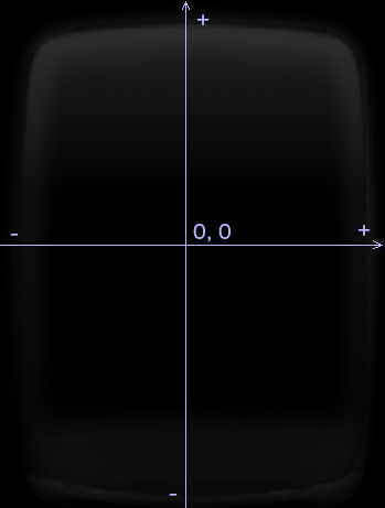
Vectrex display is structured like a Cartesian coordinate system:
(NOTE: obviously 0, 0 is in the center of the screen)
Screen updates
Since you are looking at this text, I might assume that you have already some programming experience. You most probably collected your experience programming raster screen ‘machines’. Be it computers, arcades, consoles, handhelds or whatever. If you have already programmed vector screen ‘machines’ you will find nothing new in this small section. If you on the other hand have no experience programming vector displays, let me do a little introduction first, and be ready for a whole new experience in screen updates :-).
There are nice and not so nice aspects of vector screens, as you will see.
You as a programmer have total control over the vector beam (or you let the
BIOS do the job for you -> recommended!). If you want to draw a vector you
have to place the beam at the position you want the vector to start. ‘Switch
the light on’, move the beam and ‘switch the light off’. Due to the persistence
of the screen, the vector will then be displayed for some milliseconds (I don’t
exactly know for how long). Than the vector will fade away. Most of the time
you will not be satisfied with a vector being displayed only for some
milliseconds, so sooner or later you will start thinking about how to draw a
stable image. Well, there is no secret to it, you just have to keep drawing. Draw
the vector you want to appear stable, about 50 times per second and you can
happily view a stable vector image! While the BIOS has routines for vector
drawing, even vector lists or string drawing, it does not update the screen
automatically. You as a programmer are responsible for updating the screen
regularly. If you lose too much time between these updates the display will flicker.
As a rule of thumb the above mentioned value of 50Hz is sufficient for a stable
image. The nice effect of this is, that you don’t have to worry about garbage
on your screen, if you move a ‘sprite’ you don’t have to keep track of the
background, since in the next round everything is ‘clean’ again.
Structure of program
Keeping the above said in mind, a Vectrex program most of the time has following basic structure:
-init_code-

main_loop:

 -sound update-
 -recalibration-
 -sound output-
 -input handling-
 -some other stuff-
 -screen update-

repeat main_loop until exit
The Vectrex OS and its functions
The OS is located at memory address $F000 to $FFFF (well nearly, the last few bytes are reserved vectors of the 6809 CPU). Most functions require parameters, some functions return some values. This information is most of the time passed via registers of the 6809 microprocessor. There is no ‘standard’ in what registers are used. Look at the functions for the information which registers are used. As you will know the 6809 CPU has a register called DP (direct page register), this register is used to point to 256byte pages within the memory. The 6809 can address 256*256byte pages, dp therefore can have values from 0-255. The dp register if used wisely can shorten and speedup programs, because direct page accesses are faster and shorter than extended addressing. There are two values that you will encounter frequently while programming Vectrex, as $c8 and $d0. You can see, looking at the memory map, these are direct page pointers to:
1. (dp = $c8, denotes memory from $c800 – $c8ff) RAM used by the BIOS (or the programmer)
and
2. (dp = $d0, denotes memory from $d000 – $d0ff) the base address of the VIA 6522 (VIA Versatile Interface Adapter, sometimes called PIA Peripheral Interface Adapter, only 16 bytes of the dp address space is used for VIA, since it only features 16 registers).
All output and timer functionality are regulated/accessed by that chip, it is pretty important 🙂
Memory Map
0000-7fff
Cartridge ROM Space.
8000-C7FF
Unmapped space.
C800-CFFF
Vectrex RAM Space 1Kx8, shadowed twice. (r/w)
D000-D7FF
6522VIA shadowed 128 times (r/w)
D800-DFFF
Don’t use this area. Both the 6522 and RAM are selected in any reads/writes to this area.
C800-C880
is RAM used by the Vectrex BIOS for housekeeping. (see appendix B) CBEA-CBFE is RAM used by the Vectrex BIOS for housekeeping. (see appendix B)
C880-CBEA
is RAM that can be used by the programmer!
(CBEA is used as system stack base, so not all that memory is “free”, values from CBEB-CBFF are also used by the system as interrupt pointers)
E000-EFFF
is ROM, the built in game MINE STORM.
F000-FFFF
System ROM Space 8Kx8 (r/w)
Timing
Vectrex uses a Motorola 68A09 microprocessor at 1.5Mhz. Thus one cycle is 1/1,500,000 seconds. In order to have a 50Hz stable display (which is most desirable), we must do everything we want within a limit of 30,000 cycles. The BIOS uses Timer 2 to keep track of ‘system time’. The Wait_Recal (Wait and Recalibrate) routine waits for that timer to expire before continuing and recalibrating the vector system. This BIOS timing information can be set at BIOS RAM location Vec_Rfrsh ($C83D), which is a word pointer, $C83D is the timer low byte, $C83E is the timer high byte. Thus a value of the above 30,000=$7530 would be stored to the BIOS RAM location with a sequence like:
    LDD #$3075
    STD Vec_Rfrs
My experience:
If you change the timer value, most of the time the vectors will ‘shake’ a bit,
especially if you don’t zero the beam frequently. The game speed will vary, and
nonmoving vectors (fixed, like a court or so) will annoyingly ‘shake’!
Endian
VIA
Is a little endian chip, meaning the byte order of values larger than 8 bit is first LOW than HIGH byte.
6809
Is a big endian chip, meaning the byte order of values larger than 8 bit is first HIGH than LOW byte.
The second (there are only two timers) timer (timer 1) is used for drawing vectors within BIOS vector drawing routines. Actually while drawing vectors the timer is set with the SCALE factor (which IS the low byte of the timer 1, a VIA register, VIA_t1_cnt_lo ($D004)). Thus scaling DIRECTLY relates to timing. Using a large scale factor always takes ‘a lot’ of time. If at all possible use small scaling values. See also the next Vectors->length!
Wait_Recal ($F192)
Is one of the most important functions the Vectrex BIOS has to offer. Unless you want to dig deeper into hardware programming every Vectrex program should call this function once (and ONLY once!) in each update round.
This function ensures some very important things:
- Timing
When writing a Vectrex program, you should make sure, that the main loop runs in a pretty constant time frame. A steady time frame ensures a stable image (preferable the “standard” 50Hz). But also – if you play sound or music – a stable Vectrex round ensures that the music is played correctly. Game speed – it probably also is not too bad if the game speed does not change too much because of load of the processor. - Calibration
The analog Vectrex hardware (capacitors and integrators) is prone to be not “totally” exact after a couple of loading/zeroing. Vectors can appear at slightly different locations, depending on the “history” of the previous beam movements.
The calibration routine ensures that at the start of each Vectrex round the zero placement is as exact as possible.
(This is achieved by overloading the integrators with both positive and negative values and zeroing afterwards)
Timing a Vectrex round
The BIOS functions rely on timer T2 to time a Vectrex round. The standard time for a Vectrex round is (in cycles) 30000 which is exactly 1/50s. Thus if you can achieve that timeframe you display a stable vector image with 50Hz.
For above given reasons it is not advisable to run your main loop with varying cycles – the image will appear unstable, the sound will sound crooked – and possible other things will go awry.
While Wait_Recal cannot ensure that you do not take MORE time than 30000 cycles (it does not have a time machine integrated) – it CAN make sure, that you do not run faster than that.
Wait_Recal ALWAYS waits for Timer T2 to expire, that (provided the user did not change the timer settings) means that Wait_Recal will wait till exactly 30000 cycles have passed since last setting of the timer before doing its recalibration
This also the reason you should not call Wait_Recal twice in a round – it will wait TWO TIMES for T2 to expire – while that would also ensure a stable image it would be an image with 25Hz – which looks awful!
Vectors in Vectrex relation consist of following parts.
- brightness
- Y position start
- X position start
- length in Y direction
- length in X direction
- scaling factor
Brightness
There are two ways to control brightness. First the ‘Intensity’, which is a value from 0-$7f (if the 7th bit is set there is no intensity), 0 means black, $7f means full brightness. Apart from the intensity you can vary brightness of vectors by drawing vectors more than ones or for dots leaving the vector beam for a longer period of time on the same position. For the last there is a BIOS variable Vec_Dot_Dwell ($C828), which sets a counter for how long the vector beam will illuminate the dot.
(also the brightness varies slightly with the strength/speed a vector is drawn, the faster a vector is drawn, the less bright it is (same amount of electrons spread over a greater distance)
Positions
The position of vectors are most of the time relative to the last known position. Sometimes the position is not interesting when drawing a vector, since it was set some other time, and now drawing just continues. Positioning with any function is done in relation to the present scaling factor (TIME). The programmer must keep track of the position, and should zero it now and then. If the set position is not ‘used’ within a certain time, the position will drift (my Vectrex drifts always to +, (Cartesian coordinates), a few centimeters per 10,000 cycles!). Position is given in values from -128 to +127. Most position information is set with first Y than X position.
Strength of vectors / Scale
The strength of vectors
here means something like the speed with which the beam will travel across the
screen. The scaling is something like the time, for how long the travelling
will be done. Thus it is easy to see, that travelling with a speed of 10 for a
time of 5, which would equal a travelled space of 50, is about the same as
travelling with a speed of 50 for a time of 1, which also results in a space of
50 to be covered. The only difference is, that the first will take five times
as long as the second! Strength is given in values from -128 to +127. Most
length information is set with first Y than X strength.
Some great little tips in here, especially as I’m going over my code now to reduce rom size and to improve performance… the countdown to zero in a loop is one I had never thought of 🙂
Thank you for this! It definitely layed out more of the basics better than some of the older documentation. At this point in my work within Vide I’ve got an animated face for an intro anim list I would like to inject my scrolling text into as well as a vector list of a basic play field to render after the intro in an assembly-based project. At this point I’m kind of stuck on how to start bringing this together into one program. I feel like once I get over a few more humps that I will really enjoy working with this even more.
Once I get over that learning curve, I hope to spawn a player object in the center of the playfield that can rotate and shoot projectiles much like Bedlam soon. I’m still really enjoying the VecFever cartridge and want to contribute with my own game and example code for Vide eventually.
Thx!
You are welome. If you have any questions or need a second pair of eyes on your code… give me call..
I suppose I’m one on the many people who sometimes forget that people don’t automatically know this stuff!
I couldn’t count the times I’ve described the difference betwean rasta and Vector displays in a couple of sentabces, and expected people to understand what I’m talking about!
Very good introduction to the concepts.