Just a small summary of what I have been up to lately.
Vectorblade (software)
There were a couple of “tough” weeks. At first I forced myself to enter level design. Some – perhaps 10 – days ago I had finished about 60 levels (of the 100 planed).
Finishing a game really is tough. The interesting stuff is nearly all done, now the grinding part is ongoing.
It sounds so nice and easy going to do a couple of levels – but actually to “build” a new level I nearly need at least one hour. Sure I could just copy and paste everything, but it is much nicer to have something new every other level. And/or new combinations of stuff that was introduced before. So with each level I
– either introduce new enemies
– the enemies feature some new kind of weapon or behaviour
– sometimes new attack patterns, waiting patters or intro patterns are “needed”
– and certainly each level must be tested, must not be too hard nor to easy, and possibly slightly more difficult than the level befor…
– etc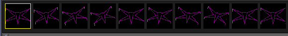
So – now one can start in level one which begins the “insect” sector and can play to level 25 and fight the “Queen”. After that some enemies appear that are arcade game inspired and at level 50 the arcade boss can be battled. Than the next enemies appear to have ancestors in some famous movie about a war in a galaxy far far away… here I am at the moment stuck at – and haven’t touched code for about 10 days or so (more on that later).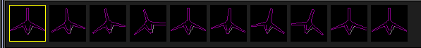
Some changes:
– the 1,2,3,4 shots have been changed, they are not horizontally arranged anymore but vertically and much smaller, this saves up to 8000 cycles on a full “blast” (but doesn’t look so bullet-hellish anymore) 🙁
– I will probably add some of the “old” shots (1,2 and perhaps even 3) as new shot variants with higher “impact”
– added a couple of new enemies
– enemies can drop “debris” instead of exploding (debris falls down, and can kill a player)
– new enemy type “shield block”, these are “enemies” which can not be hurt! They can be positioned on screen to act as a shielding device for other enemies
– I implemented the already mentioned difficulty levels (easy, normal, hard, impossible)
– the laser behaves differently depending on the difficulty (easy go “thru”, every other level – only hit the nearest enemy)
– and more stuff I can not remember
Vide / emulation
I also enhanced Vide a little bit…
– VIA debug window is a little bit faster
– saving/loading of breakpoints
– enable/disable of breakpoints
– and more small stuff I didn’t even write down…
– I still have a (long) bug list of things I should look at further…
Also I invested a little bit of time in Vectrexy (https://github.com/amaiorano/vectrexy), debugged Spike and Bedlam for quite some time… Antonio didn’t really need my help, but it was fun to look at another emulator, sources and debug some old vectrex games.
Vectorblade (hardware)
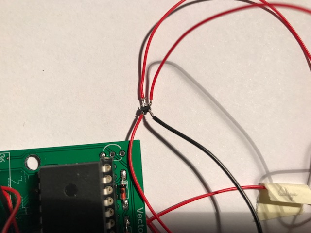
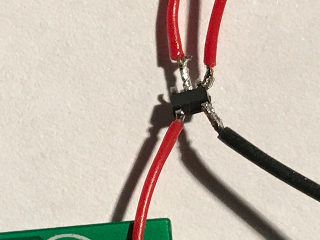
This REALLY had me frustrated for quite some time. My first pcb design was flawed (see old blog entry) because I was to stupid to put the pullup resistor for the DS 2431 access right.
That seemed to be a rather small problem. I changed the eagle schematics, ordered new prototype pcbs, which astonishingly arrived within a week. These seemed to work alright at a first glance. I have a couple of test programs for the pcb which all worked flawlessly. But after a few days, when I finally tried vectorblade I ran into problems. Rather profound problems – the game crashed as soon as I entered the first level.
The strange thing is – before the first level – I already do a couple of bankswitchings, I enter “high” memory regions (> $8000) and for the calibration I even use the DS 2431 – everything worked fine – until I entered the first level -> CRASH.
I did some serious debugging for a couple of days. The result was, that the software is correct. I programmed (more or less) a single step mode into vectorblade – and the damn single step version works, no crash. Remove single step -> CRASH.
But once I was sure, that it was no software problem, only one other part could be wrong -> the hardware, that is my PCB.
After a day of measuring, and tracing and not finding any obvious mistake, I began crying for help. A couple of helpful people came up with suggestions, and after reading the 6522 manual a couple of times my suspicion grew, that perhaps the PB6 pin of VIA can not drive two “loads” (address line A16 AND the DS2431) at least not reliably.
That suspicion became more profound, when I “disabled” the DS2431 – and voila Vectorblade works 100% fine (although without the ability to save highscores and options).
After that I ordered some “buffer” chips … only to discover hours later, that buffering will not work!
(Addendum: there are bi-drectional buffers – but I did not try those (yet) )
At least not the way I would like it to work. IF there indeed is a problem with PB6 not strong enough – than DS2431 is “dead”. Because the one wire chip must communicate with the vectrex, communicate means bi-directional. The DS 2431 chip must be able to send bits BACK to the vectrex – otherwise there is no use for the thing at all. And thru a buffer or transciever chip, there is no talking back.
Again a day I thought this through looking at different angles… but there was no solution.
– the DS 2431 device must have a bidirection connection to the vectrex
– PB6 is the only bi-directional “free” cartridge line
– for vectorblade I must use PB6 as A16, theoretically it would be possible to enable bankswitching with the IRQ line, but with vectorblade – at least as I wrote it, that is not possible
(I draw vectors in both banks, this more or less means, I can not generate a persistent interrupt state, since vector drawing in general means changing the VIA-interrupt behaviour)
One thing I don’t get though. Vectorblade DOES work with clockwork 64kB card AND DS2431 there the problem does not seem to matter – and I don’t know why!
Than Thomas told me, that the flaw might be because of an entirely different reason, perhaps PB6 IS strong enough, but still – using PB6 both as A16 and for communication with DS 2431 can generate different problems – namely, if you do bankswitching in a certain order, and remain too long in bank 0, than DS 2431 assumes you are talking to it – and it starts talking back!
Talking means sending bytes and that means it changes PB6, changing PB6 is a BAD idea if you do not do it in a controlled environment, because what it comes down to is that the DS 2431 is INITIATING some bankswitching on its own, which will certainly lead to a CRASH!
But again…. Vectorblade DOES work with clockwork 64kB card AND DS2431 there the problem does not seem to matter – and I don’t know why!
This whole stuff is really frustrating!
This was the point, where I really thought about giving up, and put Vectorblade on hiatus.
…
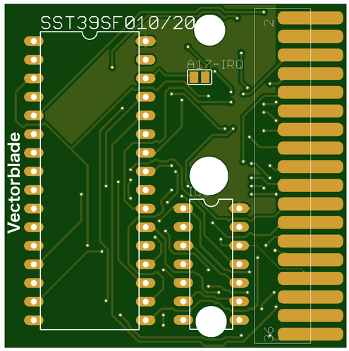
But than a new thought occured to me. Lately I have been using eEproms instead of eproms – namely I have been using a flash chip (SST39SF010A) – what if … I skip the use of a DS2431 entirely and use the flash memory that I use as “ROM” anyway?
Ok – the flash chip can only be written to xx many times (but xx for the above chip is about 100000 – if you play and save vectorblade that much – I might consider donating an additional card!).
I talked to Thomas about it and he said something like “yea, might be possible”.
There are a couple of things to consider though… flash chips can only be erased in sectors. For the SST39SF010A the sector size is $1000 – so I will not have 96k ROM but “only” 92k. I think I can live with that. I have to connect ~WE (Write enable) in the correct way and and and… but anyway…
I took out my soldering iron and tried fixing one of my cards with a configuration that might work. Also I programmed a vectrex “flash” writer/reader and tried out everything and -> it did not work.
Not at all!
Reading all manuals again, tracing everything, looking at the vectrex schematics (cartridge port) …
After a couple of hours testing and debugging I grew desperate.
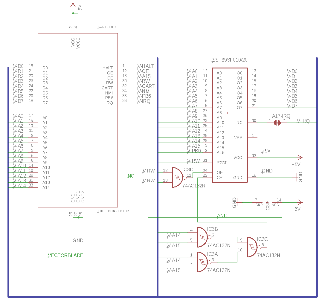
Till than I had the standard “configuration” (connection of pins from cartridge port to the flash memory). With that I mean…
vectrex side     flash side
 ~CE                ~CE
 R/~W               ~WE
 ~E                 ~OE
CE – Chip enable
R/W – Read / Write
E – Enable (also OutputEnable)
WE – Write enable
OE – OutputEnable
While growing desperate I tried the configuration:
vectrex side     flash side
~CE                ~CE
R/~W               ~WE
NOT R/~W           ~OE
Instead of connecting the (O)E to OE, I connected the inverted RW to OE.
Which “logically” seemed to make sense.
With RW:
Read = 1
Write = 0
The flash expects either OE (Output enabled) = 0, or WE (write enabled) = 0, and both (so the manual) are mutual exclusive.
And you know what – IT WORKED!
I read the device byte, I erased a sector – and the flash still works with my test program – nice!
I have not changed the high score routines in vectorblade to try it “fully” but I am rather confident right now.
BTW I only had a small SMD inverter at hand, that was really “fiddlesticks”…

So… I opened EAGLE again – and “designed” a new PCB. And again I am awaiting a prototype…
I don’t know when I will continue with Vectorblade. I feel I will only begin to continue, once I am 100% certain that the PCB problems are all fixed – that means I wait for the prototype to arrive, test it… and if it indeed does work… I will also continue to work on vectorblade.
Malban
Excellent hard work mate
Hey Malban,
So cool that you went ahead and added enable/disable of breakpoints, along with other features, to VIDE! Will make it even better to use (it’s already super great).
I had no idea that you actually compiled and used Vectrexy to debug Spike and Bedlam. I appreciate it 😀. Any thoughts on the code and debugger so far? Was it difficult to build? I assume you are on Windows?
Your hardware issues sound really hardcore. I admit I’m a bit lost when I read about it – my lack of hardware background starts to show again 😉
Best of luck!
Hi!
I didn’t actually compile Vectrexy – I downloaded your Win 64 version – and used it in parallel to Vide, just like you did.
I haven’t set up a decent Win compile environment.
I like your trace output to text with that you can navigate quite easily and independendly of any “ongoing” stuff…
I also like your CLI approach for the debugger – although at first for the breakpoints I tried deleting one with its address rather than its index – which resulted in a crash, perhaps you might look at that.
In Vide I took a different approach (as you saw) – one “cool” feature I use often within Vide is the ability to “take steps back”, to actually undo emulation steps.
I find that often very useful for debugging vectrex stuff. But than – that was my main interest, to have a development environment…
HW
Nope – not hardcore – this is the first dabbling in anything hardware related I ever did. Still have huge amounts ahead of me to learn…
And yeah – the comments wait for my approval – they are not displayed right away – otherwise the blog would be cluttered with SPAM…
Ah right, I though since you mentioned looking at Vectrexy code, it implied you had compiled it. In any case, I’m glad to tried my debugger.
I will add the ability to delete breakpoints by address since that’s actually useful. The reason I don’t have that is I was trying to model my debugger after gdb, which works this way (add breakpoint by address or source line, delete by index). At the very least, it shouldn’t crash.
The stepping back thing is super cool! I would need to rearchitect quite a bit to support that, or look into it when I add state saving support. My nes emulator supports going backwards, but it’s not at the instruction level; rather, I save states at 60hz up to some limit (1 minute worth) in memory, then allow the user to hold a key to start reversing. This is super fun to use to cheat your way through a game 🙂
Great stuff, a very interesting read… this is gonna be epic!
Did you prototype your circuit on a breadboard first, or go straight to PCB? I’d always make a proto, there’s no way I’d get it right first time on a PCB!
Great to see and hear about the progress 👍
What I could breadboard – I did.
But it was most of the time easier to take a clockwork pcb and change/wire it to the circuit I wanted… at least for me, since I have about a 100 “flying” around :-).
Back from holidays, reading all these amazing stuff…Seems you made a giant leap forward here.
Lots and Lots of hours of development both in software and hardware….
I silently follow you, admiring your fine progress so far!
Thanks for the update 🙂