The last days (since I got it) I have been looking at VPatrol.
I played it a lot – and also examined it a lot. Its a wonderful game – which really goes to the limit of what the vectrex is capable of. It does not display in 50Hz but that is a personal idiosyncrasy of mine – and doesn’t effect gameplay in any way.
It just would not have been possible to squeeze all the odds and ends into it, which makes it into such a polished game.
I am still in the process of looking closer into it – but I’d like to share some of my “discoveries” (Kristof – doesn’t mind my sharing – I have been in contact with him).
Calibration
The way Kristofs calibration routine work does (nearly) cost no extra cycles and is astonishingly efficient. Kristof uses the so called “Zero Reference” of the integrators.
Apart from some testroutines of mine I cannot think off hand of any other vectrex program that use the “zero offsets”. – Well apart from zeroing them. At every WaitRecal (and every Reset0Ref) the BIOS sets the zero reference to (guess what) zero!
Technically as the name implies the zero reference is the base (zero) reference to the voltage that is summed by the integrators. Look at the following extract of the schematics.

Red: y integrator
Green: x integrator
Yellow: zero signal (which is used to control the switches, which can short circuit the integrators (over 220Ohm) )
Blue: zero reference
All values that you (as a programmer) put into the analog parts of the vectrex go thru the DAC (digital to analog converter) (not shown above). The DAC converts the byte values (-128 to 127) to analog “values” (the DAC actually converts digital signals to respective current which in turn is transformed to voltages, which go thru the analog MUX and reach the left side of the above image – in case of the zero reference PIN 14).
At the moment I am not quite sure whether the voltage received ranges from 0V – 10V or -5V to +5V – if anyone knows – please tell me 🙂 – despite my ramblings I am not well versed in electronic stuff.
(Addition: It is actually ~ -2.35 to +2.35 Volts, see: Proboard message board)
Anyways the range of voltages that can be set is 10V – the minimal steps the analog values can change is 10V/256 (conversion of digital values) – about 40mV.
Now – Kristof “discovered” that a calibration can be done by changing the zero reference. Only thing is, the step range of 40mV was to big. If you change the reference value slightly to much you overcompensate the faults you want to compensate.
Meaning – if the vectors are to much to the left – and you try compensate with one 40mV step – the vectors are not centered, but offseted to the right. Kristof needed steps SMALLER than 40mV!
Now what is the zero Reference? How is it “stored” – if you look at the above image at the beginning of the blue line you see a capacitor (305) with 0.01uF.
A capacitor is charged over time like:
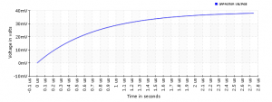
(I don’t know the resistor value to use – above I guessed 75 Ohm – but I guess in reality it would be slightly more).
Setting the zero reference is in fact charging a capacitor. Setting a value “smaller” than the pre-existing value is a discharging.
Ok – long talk.
What Kristofs calibration routine does:
- write the calibration value to Zero Ref (digital value: -128 – +127, depending on what value you set with your joypad)
- wait for a few cycles
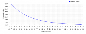
- “discharge” the capacitor with a fixed setting of digital -1 (-0.04V) for 4 cycles (1 cycle ~ 0.6us)
My guess is that Tau in the discharge equation is “about” one cycle (0.6us) – that would mean after 4 cycles only about 2% of the “original charge” (in respect to the target charge) would be left.
Anyway – again – if these numbers are totally correct or not does not really matter – it does work – and the theory behind it is sound.
With the described method Kristof is able to set the Zero Reference to analog values in steps that are way smaller than the steps the DAC can deliver! And thus a real FINETUNING is possible.
Vide:
For the Zero reference I implemented a new class “Capacitorial” and the zero ref is now a instance of that class:
public Capacitorial c_alg_rsh = new Capacitorial(75, 0.00000001);
and the value of the zero reference is calculated at each “step” with relevant formulars. And it works!
At some stage I probably should do that for integrators and other sample/hold stuff as well – but that is the future!
To be continued…
Malban
That means if you were to use Kristofs calibration routine (which nearly costs no extra cycles) in Karl Quappe there is a possibility to align the Vector graphics behind specific regions of a coloured overlay? That would mean a multi colour overlay with transparent colour bands could be used to make the middle island and home bank green, the water blue, and the road another colour. Don’t worry not requesting only dreaming……
I do not say it is impossible – but the routines I described (if you look at VPatrol) is the first part of his calibration, which relates to vector alignment in large vectorlist, basically “drift”.
The positioning alignment is a different section.
If you are dead set on doing a Karl Quappe overlay with different lane colors – PM me – and I’ll try to do a special alignment version…
hehe, thx, but no particular desire from me, as too many other projects on the go – thanks for offering though.