Memory/Size
Vectrex in its original state can only address up to 32kB of “cartridge ROM” space (0x0000 – 07fff). Vectorblade is (in Vectrex relation) a huge program, the overall size of Vectorblade is 192kB – 6 times the size of the above “maximum”. Two different technics were used to realize the usage of 192kB of memory.
- Extending the addressable memory
Using a very easy to realize circuit on the cartridge pcb one can enable the usage of an address space of 48kB (0x0000 – 0xbfff). - Bankswitching
Vectorblade uses 4 banks, this mean 4 times 48kB of memory. The banks can be switched very fast during execution and is thus for the user not noticeable. Bankswitching is achieved using the PB6 line and the IRQ line of the cartridge port. Both lines can be altered using VIA features.
Originaly the game was planned to have a size of 64kB – during development however it was clear that more memory was needed – thus ways for expanding the memory were engineered. However, since the planning was different from the onset and more or less changed “organically” along the way, the whole source code is not as well structured as one would like – you will notice that while reading further.
Banks
From a Vectrex point of view, each “bank” is an own “cartidge”, disjunct from any other cartridges (or banks). What holds these different cartridges (banks) together is the contents of the RAM – where all game information is stored. Coding/and compile wise each banks is programmed and compiled seperately, theoretically there is no need to even keep the sourcecode in the same directory or anywhere near each other.
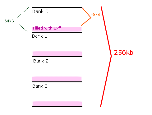
The results of the assembler (four different seperate “bin” files of 48kB) are concatinated together to form a single 192kB “bin” file.
(actually each 48kB is filled up with 0xff to a size of 64kB, and all 4 resulting 64kB bin files are concatinated to form a 256kB bin file).
Bank ordering
Due to the “default” state of the bankswitching lines (IRQ/PB6) the order of the banks is reversed to the “natural” order.
If you boot up your vectrex the default states of the bankswitching lines are:
IRQ = 1
PB6 = 1
The number of the current active bank is built by representing the two states as a binary number:
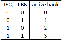
So – Vectorblade starts up in bank 3.
Bankswitching
For a first read on bankswitching, please head over to an older blog entry:
1st of June – “Faulty” VIA vs “INC”
In order to accomplish bankswitching we have to change the values of
PB6 and/or
IRQ
which are passed to the cartridge port.
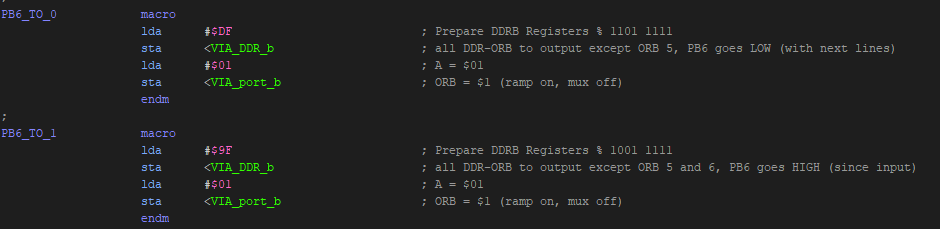
PB6 is the “classic” bankswitching described above.
Code wise:
IRQ
… is a bit trickier. In general you must ensure that VIA issues an interrupt, and that after the interrupt was issued the state of the interrupt flag is not changed (for bank 2 and 3 this is easy, just disable IRQ generation, there is a special VIA flag to disable IRQ generation in general!).
If an interrupt is issued – the interrupt flag is cleared (zero active). If there is no interrupt pending, the flag is set.
There are different ways, that VIA can issue interrupts, but only two are sensible in our situation:
a) Timer T1 interrupt
b) SHIFT-register interrupt
Like the names suggest:
a) the interrupt is (can be) issued when T1 reaches zero
b) when a complete SHIFT cycle is done by the shift register
If you know your way around VIA and Vectrex you might notice, that both (T1 and SHIFT-register) are essential to BIOS routines that draw vectors!
a) T1 is part of the length definition of a vector (for how long is the beam switched on while moving), T1 controls the ~RAMP line!
b) The last shifted out “bit” is actually the state of the ~BLANK line of the vector display circuit inside the vectrex and is thus responsible to switch the vector beam on or off.
Both, the ~RAMP and the ~BLANK line can be altered without the use of the T1 or SHIFT-register though (only the BIOS does not offer these alternatives).
In order to use either a) or b) (and be able to draw vectors within bank 0 or 1) you have to create your OWN vector drawing routines.
Your routines either have to avoid T1 or the SHIFT register, otherwise while drawing vectors an unvoluntary bankswitch will occur.
In Vectorblade (depending on what I want to do) I use either the SHIFT-IRQ or the T1-IRQ. I will not explain here when I use what, and how the different vector routines work, but you are welcome to investigate the sources.
Main files
Each of the 4 banks has a “main” file. The file, that includes all other needed files, to be assembled into one of the above mentioned “bin” files.
Cleverly these main files are called:
mainBank0.asm
mainBank1.asm
mainBank2.asm
mainBank3.asm <= cartridge starts here!
In order for these bank files (remember: in reality different cartridges) to work seamlessly together certain conventions must be met.
In Vectorblade the first (meaningfull) lines in those mainfiles are always the same, namely (example bank 3):
CURRENT_BANK EQU 3
 include "commonGround.i"
First I set a variable (for possible later if then /else clauses within the source), which bank we are currently “in”.
Secondly I load a “commonGround.i”. Within in that file (and other files included from there) the RAM locations, structures, variables and constants are defined. Also (later more on that) – a special set of routines reside here, which must be exactly the same and positioned at exactly the same memory addresses within each bank.
Calling the banks
How do I call a subroutine in another bank, or jump to another bank?
Pre requisite: read the blog entry from above link (at least the grey boxes)
Issue the call
I realized the call (or jmp) to a different bank as follows:
a) load register X with the address of the function in the other bank
b) call a “special” routine in the save zone. The special routine does:
– switch to the appropriate bank
– if a jump: jumps to the given address in X – done
– if a subroutine: jsr to the given address in X
after return from the subroutine:
switch back to the bank of the caller
return
Sounds easy enough, and actually really IS easy, appart from the fact, that there are quite a few combinations that might be needed.
e.g.
– jumpTo0
– jumpTo1
– jumpTo2
– jumpTo3
jsrFrom0To4
jsrFrom1To4
jsrFrom2To4
jsrFrom3To4
jsrFrom1To0
… etc
Also the above might need another “implementation” in case you differ between T1 interrupt and SHIFT.
I myself have not implemented all possible permutations of calls, but quite a few.
What was there first, the chicken or the egg?
This is a question, that might also be asked while using routines with different banks – at least as implemented currently in Vide (I should at some stage change the implementation – thing is, it works – and thus there is no direct need to change…).
Please read: 8th of May – one month gone by.
Where this question is answered!