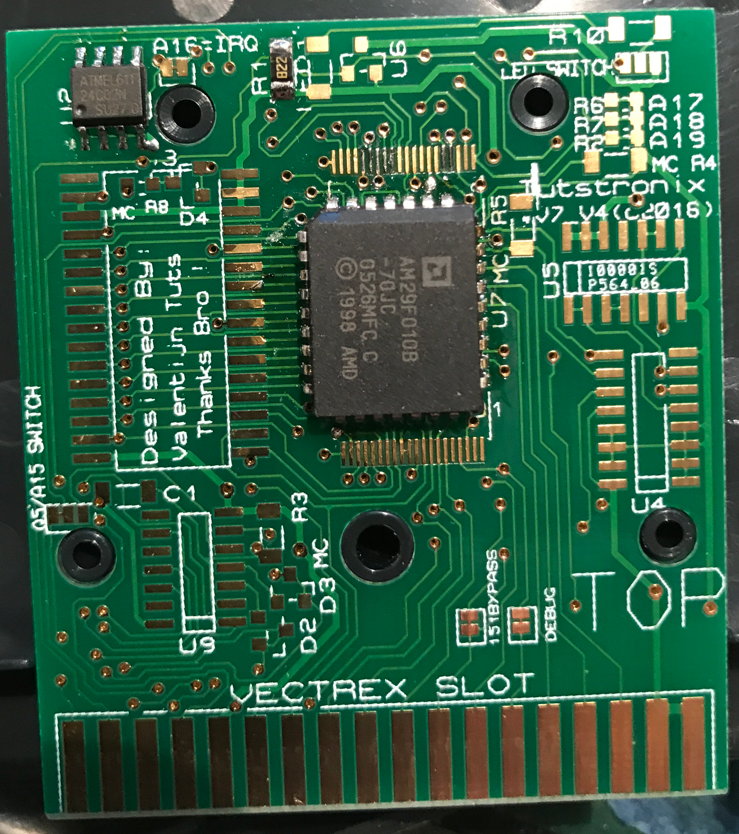
This is an image of the interior of my VPatrol card. Today I would like to concentrate on the upper left corner:
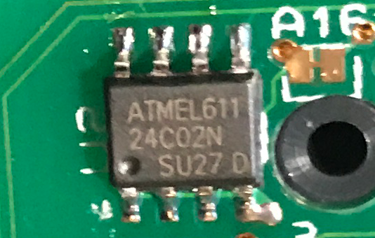
That is the eEprom Kristof uses to store calibration information, high scores, acchievments and options. You might say “so what” – it is sort of a common thing now to include a permanent saving mechanism to cards.
I dare you – to look a bit closer.
This is the “full” naming/specs: ATMEL 611 AT24C02N 10SU-2.7
- 2,7V
- “U” designates Green Package + RoHS compliant.
- Package 8S1
- 8-lead JEDEC SOIC
- AT24C02, 2K Two-wire Serial EEPROM: Internally organized with 32 pages of 8 bytes each, the 2K requires an 8-bit data word address for random word addressing.
Although the datasheet doesn’t say it probably due to copyright reasons this is a I²C compliant device.
TWO WIRE
The “extraordinary” above is the word “two” instead of “one”.
Before VPatrol all storage devices inside Vectrex cartridges were one wire devices – a tradition that began with Alex Herberts “Protector”.
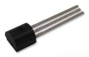
One wire eEproms (as the name suggests use GND, some Voltage and one Pin for communication) – thus these device often come with 3 connection pins and look a little bit like a classic transistor.
This “one” is/was due to the fact, that the vectrex cartridge port only sports 1 pin that is “programmable” from the Vectrex side. That pin (cartridge port pin 35) is connected directly to VIA and can be read or written to by doing some stuff with (or to) the VIA chip. Namely that is VIA Pin 16 – which, since it is addressed by the 6th bit of Port B, is also often refered to as PB6.
PB6 is famous for communication with all kinds of cartridge internal stuff, like:
- bankswitching
- eEproms
- Thermometers
- …
Anyway…
The above mentioned AT24C02N 10SU-2.7 (which I will in the following only reference as “Atmel”) is a two wire chip. This means it needs TWO pins to communicate with Vectrex!
- SDA: Serial Data
- SCL: Serial Clock Input
- there are more pins (address pins if you have more than one I²C devices, write protect, etc) – but these do not concern us here
In order to use the chip you must be able to write to the cartridge with one other external (cartridge port – Vectrex) signal.
How is that possible? -> IRQ!
The service manual is not very easy to interprete in this regard – cartridge pin 36 is connected to the ~IRQ pin of the processor.
VIA can generate interrupts (by timer, shifts, control lines etc), the schematics show the VIA ~IRQ pin connected to the RAM chips – which is nonsense. What is not nonsense is the fact that ~IRQ signals of VIA must reach the CPU, otherwise it would not be possible to generate interrupts at all (by VIA).
And once the connection to the processor is made it stands to reason that the same TTL – level will be available at the cartridge port (at said pin 36).
Thus by generating an interrupt (~IRQ = 0) or by no interrupt (~IRQ = 1) you can programmatically change the value of pin 36 of the cartridge port!
VIA interrupts can be very flexibly generated, enabled, disabled etc. Also – even if an interrupt is generated, that does not mean the microprocessor has to interrupt its work – you can (conditional code register – bit 4 – Interrupt Request Mask) tell the processor to ignore interrupts. So if you do it right you can set/unset the interrupt to your likings without disturbing your code.
So how to communicate?
Well essentially like it is stated in the datasheet. But to use Krisof’s words:
Me:
“You use the T1 Timer interrupt to put “signals” on the cartridge IRQ port and thus SCL?
I didn’t know that was possible – but your source suggestest it…”Kristof:
“Yes, correct. The PIA-IRQ pin is in fact an open-drain output and if you look on the vectrex-schematics, a pull-up resistor of 3K3 is already installed on the logic board. The PIA-IRQ pin goes low depending on the flags set in the IER and IFR registers. So, for example, by letting T1 go timeout, you can generate an SCL low signal.
Actually, you can manage the IFR and IER in such a way, that you can always create an IRQ low or IRQ high signal.”Me:
“This makes the serial code much more compact than in Vector Pilot – or so it seems…”Kristof:
“Yes. It makes it also more robust since classic I²C is by definition a quite robust protocol. Actually, when the program is doing bankswitching via toggling the PB6/SDA-line, it does in fact also massive amounts of START/STOP conditions towards the connected I2C-chip. But this doesn’t seem to be a problem for the I2C-chip.”Kristof:
“AND THIS MEANS ANOTHER BIG THING: we now can control 2 binary signals PB6 and IRQ, which means extra bankswitching! So instead of having just 2x32K-banks,we now can have 4x32K-banks. “
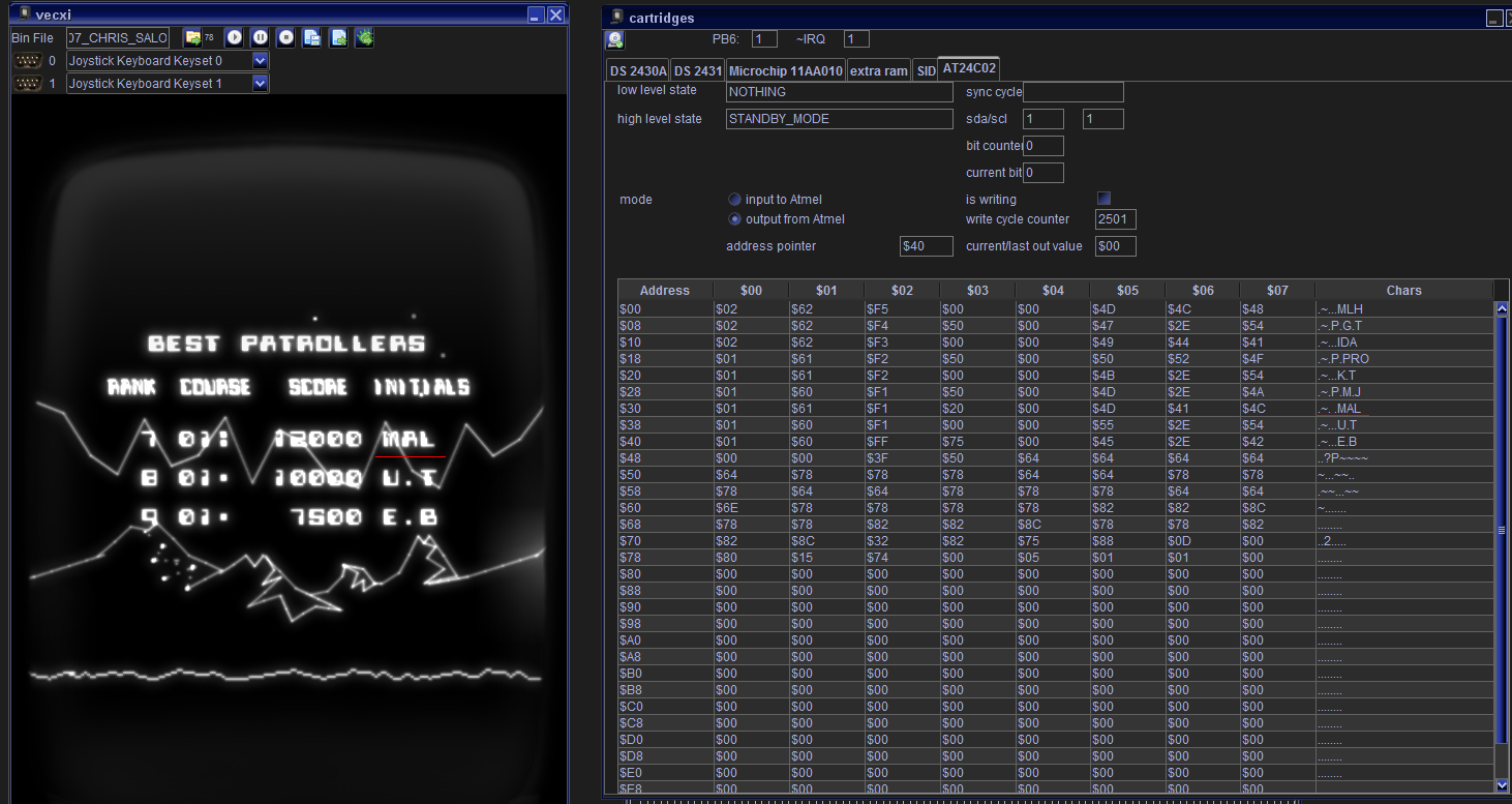
Vide:
I added emulation of the Atmel chip. So if in fact you have a binary ROM of VPatrol and for whatever reason want to play it using Vide (which defenitly does not compare to the VPatrol experience on a real Vectrex) – it saves highscores and other stuff – starting with the next version I upload.
Malban
I won’t pretend to understand very much of these Vector Patrol posts but they are fascinating all the same!
Great detective work.
You mention bank switching traditionally being 2x32k banks on Vectrex, but with some additional latches e.g. 7474 or 74138 decoder, you can probably switch in multiple banks using the standard address lines on the cartridge port, and not have to do the full 32k. I used the do this with a Z80180 back in the day, which is a Z80 that has a built in memory manager that allows it to use 512k. See here for example circuits for a standard Z80: https://www.eevblog.com/forum/beginners/z80-single-board-memory-bank-switching/
Here’s a question: On Vectrex, if you’re bank switching 32k, do you have to put your base code in both banks, so it still works when they are switched? With Z80180, you set up 3 separate address spaces, common, bank 1 and bank 2, with common not being switched i.e. you only switched 16k instead of 32k, for example for banks 1 and 2.
Since on vectrex it is so “easy” to use the pb6 pin as an additional “address”-line it has become the standard way todo bankswitching. All currently available bankswitching schemes switch 32k from $0000 to $7fff. So yes for these bankswitchings you must have the same base code in both “banks”. Although you can use the RAM from $c800 – $cbff and place the switching routines there (for VecFlash and VecMulti this is compulsory, for “normal” PB6 it is more optional).
The “multiple” bank switchers (like vecFlash/vecMulit) also only use PB6 but they use different “timings” of the signal to “count” the bank that should be set. VecRAM is slightly different – but I have never looked into that – and haven’t added for emulation either (yet – have to ask Franck if I can borrow some of his code…).
Recently Thomas Sontowsky implemented an additional bankswitching scheme that can be used with his newest VecFever ROM. There he uses the above mentioned $0000-$7fff as “base”, which stays the same and he can switch in different 16kB blocks of memory to the address $8000 – $bfff.
With this bankswitching he can add (at the moment) 4 addtional 16K banks. Switching is done with “hotspot” locations $c000 – $c003.
At one time he though to further use the VecFevers abilities to enhance the bankswitching to load up to 32 different 16kB blocks – but I don’t know the current status of that…
I came back to this when thinking about AT24C02N. I would like to be able run Forth on the Vectrex and have it download a binary via the serial port and run it. That’s quite straightforward for a raw binary with no cart header. But it’s more tricky when it does have a cart header and expects to be in RAM from $0000, I would have to switch Forth out before booting the cart binary. My thought was also to copy switching code into the Vectrex 1K RAM and execute from there, like it appears the VecMulti is doing. Thanks for the earlier response that confirms it should be possible!
Wow, I just read this post again. What you/Kristof are saying is that you can cause the VIA to create an IRQ interrupt to the CPU that your Vectrex code ignores, but that IRQ line also carries to the cartridge port and can be used for additional address decoding, or indeed an I2C line. That isn’t just cool, that’s sub-zero.
Correct.
Kristof used this for I2C and in Vectorblade I used this as an additional addressline for bankswitching.