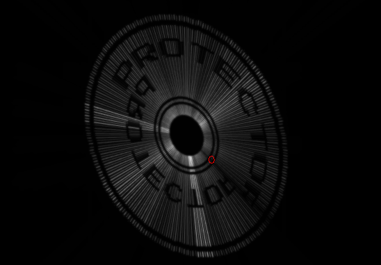
You know – I really like the stuff that Alex Herbert did.
Above is the an image of the “credits” of his Protector/YASI release, a spinning disc with two scrolltexts.
It looks stunning on a real vectrex.
I always was intrigued by it.
A week ago I thought. “Just for fun – let’s try it out!”
Note! – I did NOT reverse engineer his code. Below stuff is not “finished”, cleaned up or optimized, just quickly thrown together code – I did that in about 4 hours, so don’t judge the code to harshly.
Step one – a circle.
I had never given it much thought before. How would I realize a “demo” like that?
Obviously you need some form of circle, radialy printed from some (no – THE) center.
Luckily I have used circles before – so I now how to handle them :-).
I could get the coordinates from the ROM, a function – or just a lookup table. Since I am lazy and Vide supports lazyness and I wanted to get on with it – I took the most simple solution and inserted circle data into my ASM:

Actually you can’t see it, but I “doubled” the data (twice going from 0 to 360° stepping by 1 degree – that is actually already nearly 1,5kB of data! Yeah wastefull – but what the heck I am playing around here). The double data makes it easier later when I have to print the circle starting at different angles. I do not have to worry about out of bounds angles – if I start at angle – lets say 40 I end at 40+360 = 400 degrees. By doubling the data I do not need to check the 360° max.
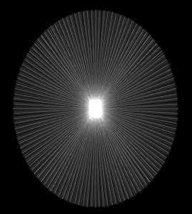
A Loop to print a disc than looks something like:
drawDisk
                    lda      #$7f
                    sta      <VIA_t1_cnt_lo
                    lda      #(360/(6/2) )+1
                    sta      diskLineCount
                    ldy      #circleData
                    ldd      diskAngle
                    leay     d,y
next_line_a_disk:
; zero
                    ldd      #(%10000010)*256+$CC         ; zero the integrators
                    stb      <VIA_cntl                    ; store zeroing values to cntl
                    ldb      #ZERO_DELAY_P                ; and wait for zeroing to be actually done
; reset integrators
                    clr      <VIA_port_a                  ; reset integrator offset
; wait that zeroing surely has the desired effect!
zeroLoop_a_disk:
                    sta      <VIA_port_b                  ; while waiting, zero offsets
                    decb
                    bne      zeroLoop_a_disk
                    inc      <VIA_port_b
                    dec      diskLineCount
                    beq      endDrawDisk
                    LDA      #$CE                         ; Blank low, zero high?
                    stb      <VIA_cntl                    ; store zeroing values to cntl
                    ldd      ,y                           ; y, x coordinate. only every 3 angles
                    leay     6,y
                    jsr      Draw_Line_d
                    BRA      next_line_a_disk             ;Go back for next scan line

endDrawDisk
                    rts
Step 2 – changing to Raster
Obviously this looks still nothing like the “demo”.
The disc should actually display text. Text with vectrex often means raster data. To display some raster data two things must come together:
a) have some raster data
b) have routine that prints raster data
a) have some raster data
For my own quick trials I looked around my directories and found:
 The title of Karl Quappe!
If that one works out – perhaps later I will create a FONT and display some text – first some baby steps.
Ok, let me “lose” a few words on that – some important configurations.
a) switch off “generate bi directional data”.
b) switch on “vertical vectors”
And select the selection of the raster data you want to use.
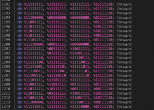
The generated data will than look something like (this is actually the first “K”):
b) have routine that prints raster data
The routine printed above draws just a “line” from the center to the circle coordinates.
Instead of a “straight” line we should print a “patterned” line – and the pattern should be the “patterns” gotten from the raster data.
Patterned lines are always printed by using different “patterns” for the shift register.
So in the above routine in “general” the “jsr Draw_Line_d” must be replaced with a “print one raster line”.
If you replace the last 5 lines of above subroutine with a “raster print” routine than something like that is the result:
drawDisk
                    lda      #360/(6/2)
                    sta      diskLineCount
                    ldy      #circleData
                    ldd      diskAngle
                    leay     d,y
                    ldu      imageStart
next_line_a_disk:
; zero
                    ldd      #(%10000010)*256+$CC         ; zero the integrators
                    stb      <VIA_cntl                    ; store zeroing values to cntl
                    ldb      #ZERO_DELAY_P                ; and wait for zeroing to be actually done
; reset integrators
                    clr      <VIA_port_a                  ; reset integrator offset
; wait that zeroing surely has the desired effect!
zeroLoop_a_disk:
                    sta      <VIA_port_b                  ; while waiting, zero offsets
                    decb
                    bne      zeroLoop_a_disk
                    inc      <VIA_port_b
                    LDA      #$CE                         ; Blank low, zero high
                    stb      <VIA_cntl                    ; store zeroing values to cntl
                    LDD      #$1880                       ; a→AUX: b→ORB: $8x = Disable RAMP, Disable Mux, mux sel = 01 (int offsets)
                    STA      <VIA_aux_cntl                ; Shift reg mode = 110 (shift out under system clock), T1 PB7 disabled, one shot mode
                                                          ; first entry here, ramp is disabled
                                                          ; if there was a jump from below
                                                          ; ramp will be enabled by next line
                    lda      diskLineCount
                    beq      endDrawDisk
                    suba     #1
                    sta      diskLineCount
                    lda      #4                           ; number of SHIFT bytes, each line than x*18 cycles in "draw"
                    sta      tmp1
                    lda      ,y                           ; y coordinate
                    sta      <VIA_port_a                  ; Y To D/A output
                    STB      <VIA_port_b                  ; ramp off set mux to channel 0, Enable mux (set y)
                    incb                                  ; B = $81
                    STB      <VIA_port_b                  ; Disable RAMP, set mux to channel 0, disable mux
                    lda      1+OFFSET,y                   ; x coordinate
                    leay     6,y

                    STA      <VIA_port_a                  ;Send it to the D/A (X)
                    LDA      #$01                         ;both to ORB, both ENABLE RAMP, mux off
                    STA      <VIA_port_b                  ;[4]enable RAMP, disable mux
                    BRA      LF4CB_a_disk                 ;[3]

LF4C7_a_disk:
                    lda      ,u+
                    STA      <VIA_shift_reg               ;[+4]rasterout of char bitmap "row" thru shift out in shift register
LF4CB_a_disk:
                    dec      tmp1
                    BPL      LF4C7_a_disk                 ;[+3]Go back if not terminator
                    LDA      #$81                         ;[2]disable mux, disable ramp
                    STA      <VIA_port_b                  ;[4]disable RAMP, disable mux
                    LDA      #$98
                    STA      <VIA_aux_cntl                ;T1→PB7 enabled
                    BRA      next_line_a_disk             ;Go back for next scan line

endDrawDisk
                    rts
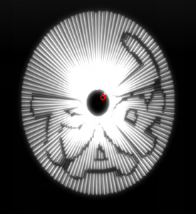
A first “Karl” disc. The discs size is dependend on two factors:
- the strength of the vectors (that are really the circle coordinates, I chose to have values from -128 to +127 -> “full” size)
- the number of “raster” bytes. Usually a font would be only 1 byte. The image I chose for lazyness has a “height” of 4 bytes (4*8 pixel = 32 pixel height in raster language)
So the above “disc” is a raster image of 32 x whatever length. Since the usual raster font would have a height of 8 pixel I could actually display on the above disc (with the same size) 4 rows of “text”.
The “spinning” of the disc actually is only a change of the “start” angle.
Rotation
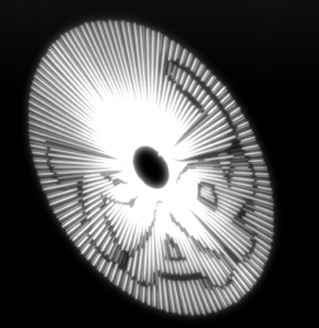
A very nice effect of Alex disc is the rotation, which gives the impression, that the disc is beeing viewed from different angles.
I had to think about that a bit – till it dawned on me, that the different “view” angle is nothing else than a different “circle data” offset for x and y coordinate.
So if a “normal” circle is printed using the data like:
y = circle Data + angle
x = circle Data + angle +1
The only thing I had to do is take the coordinates with “offsets”, like:
offset = 10°
y = circle Data + angle
x = circle Data + (angle+offset) +1
If the offset changes slowly over time, than we have the “rotation” effect, following image was taken with a fixed offset of 20°.
In the above listing the “OFFSET” would be = 40.
A little bit fine tuning…
For my personal “final” I print 5 shifts, the inner “shift” raster ensures a correct disc hole and two stripes. I changed the “outer” bitmap to also display a little “stripe”.
I added an intensity setting for each line, so the disc “shimmers” a little.
Alltogether for about 4 h work it looks good.
It does not look as polished as Alex disc, at least the intensity settings of his are cooler. Also I never did the real “font” stuff (scrolling in different directions is peanuts…). But it was a little “explorational” coding – I probably will not use it further.
Astonishingly the current version refreshes well under 50Hz. I think it is one “shift” bigger than Alex disc.
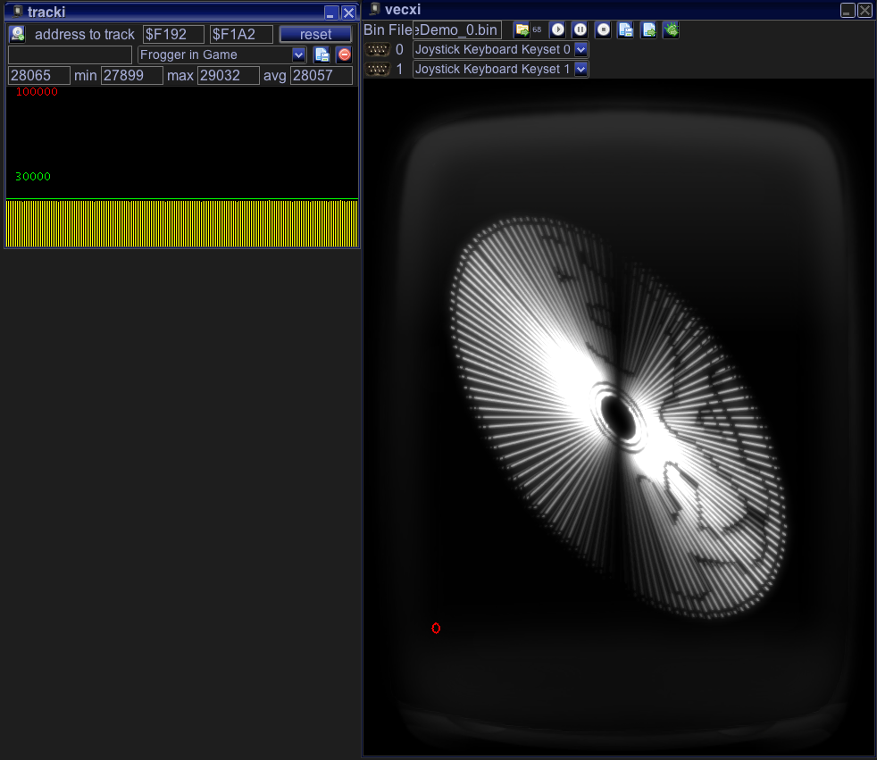
… and a short video. If I ever clean up the sources – I will include them with Vide.

I like the results of this experiment very cool looking in the video.
Looks amazingly cool! I understand you’re a busy bee lately so many wonders are coming up soon on our screens…Cheers!
Hm – actually I feel I am a bit Vectrex lazy atm 😉