We all know Professor Dr Peer Johannsen (see e.g. Vectrex Academy 2022) likes to experiment and go to the depth of things. During his recent adventures to get a Vectrex to run with an upgraded CPU (Vectrex using a 6309) he had to change several BIOS functions (because of speed differences).
(Interesting side note -> look at: Proboards Redemption of random to learn more about Vectrex Randomize function)
The PrintStr function was amongst those. Now we have looked at strings in the past. Mainly under the aspects:
- how can we speed up string printing
- why are strings often italic
For these aspects please see my old blog entries: Blog entries about strings.
Some String background in short:
Italic:
In short – strings are slanted when your vectrex has a horizontal drift.
The more drift, the more italic. The longer a string, the more italic.
Since the drift moves the vectorbeam in one direction – the longer the beam is not reseted – the further the drift distance. The longer the string, the more time needed for printing -> the more italic.
Size/Timing
The time to print a complete string is only dependent on the number of chars within the string – the size (width/height) of the string does not change the timing in any way.
Each letter needs exactly 18*(7+6) = 234 cycles to be drawn (for a complete string it is more than the sum of its letters, since the routines must be setup first).
Font
Vectrex letters are raster fonts in a 7×7 matrix – seven rows and seven columns.
(see: bit dump of Vectrex font)
Each row of a character is represented by one byte, and each character consists of 7 bytes.
(the last bit of each byte MUST be zero and can not be used, otherwise strange looking artifacts may be drawn on screen!)
The DAC!
(Datasheet of a vectrex compatible DAC: DAC 0808 – also comes with Vide)
During his work replacing the original PrintStr routine – Peer did several experiments – one of which included printing the same string with different “Vec_Text_Width” settings. This variable represents the horizontal size of a string (hence – WIDTH). In other Vectrex terms (at least my own), this is the same as the strength/speed with which the vector beam moves.
He discovered that with different width settings the slanting of the text on screen changes – sometimes even “dramatically”. Befor we go further into this – let us recall how the vectrex works…
Vectrex explained!
A short recall on how the vectrex moves the beam – pls see several other blog entries or the WWW for a more sophisticated explanation.
The Vectrex is half a digital machine (processor, RAM, VIA, ROM…) and half an analog machine (vector monitor, placement of the beam, brightness etc).
In very easy terms – how is the electron beam placed/drawn on the CRT (cathode ray tube):
On one end of the tube an electron beam is emitted – if there are MANY electrons, the phosphor on the inside of the screen will start to glow -> you see a dot.
If there are not so many electrons – you will not see anything in front of the screen (unless you turn brightness WAY up – in which case more electrons are present again).
The electrons usually go straight to the tube -> there will be a dot at the center.
However – on each side of the tube there are metal plates (left/right and bottom/top). If they are charged (positive/negative voltages) they can “repell or attract” the beam depending on the amount of charge – you are able to move the beam in any direction you like -> you can move the dot.
The charges on these plates are generated by the vectrex logic board – the charges are analog voltages and do not belong in the digital world.
The Vectrex logic board however has a component called DAC (Digital to Analog Converter) – which can do exactly that – convert a digital value (8bit – each bit either a logical 1 = 5 Volt or a logical 0 = 0 Volt) to an analog value between 0V and 5V.
So a digital 255 will be converted to 5V and a digital 0 to 0V and every other value something in between.
(You experts – bear with me, I know the voltages are “fake” and I also know that the DAC works with current rather than voltage – but lets keep it simple – ok?)
This analog voltage is than connected to an integrator, which accumulates these voltages over time to a final voltage which is connected to the CRT “plates” which control the vector beam.
The values I call strength/speed and which are the defining elements of every vector on the vectrex – all go through the DAC into the above mentioned analog vector generation electronic. The VEC_TEXT_WITH -> exactly the same!
Just for info: The DAC is unsigned!
The digital strength values range from -128 to +127 (zero being the center, negative values are below or to the left, positive values are further up or right).
The DAC however only knows values from 0V to 5V – (unsigned values), it follows that the digital 0 (zero value) is in the analog world not 0V but half the maximum voltage in our example a digital 0 would be converted to 2.5V.
Ok. What has all that todo with the slanting of Strings?
The PrintStr routine is very sensitive to positioning irregularities. One such irregularity was identified long ago – DRIFT!
But as it turns out Peer discovered another irregularity -> the DAC!
The Datasheet tells us the DAC comes with tolance of 0.19% which sounds very precise! But as you will see – even this may cause strings to be additionaly slanted!
(also: Vectrex DACs are about 40 years old, I wonder if those 0.19% were ment for DACs with this lifetime!)
To understand the following I must again at least recapitulate how strings are drawn by the BIOS.
How Strings are drawn – in short!
Each character actually is a bitmap (not vector data). Bitmaps on the Vectrex are usually put on screen using the SHIFT register of VIA.
You put one row (of a character) at a time into the shift register and start shifting. Each 1 bit switches the beam on, each 0 bit switches the beam off – all this is done while the beam moves from the left to the right.
Lets say you print “THIS IS A TEST STRING!”, the count of characters being … 22.
Since you want to print the string from left to right VEC_TEXT_WIDTH must be positive – let us say VEC_TEXT_WIDTH is 80.
Than with a speed of 80 the vector beam moves from left to right and while moving the vector beam is switched on and off by the shift register.
Each row of a single character needs 18 cycles (just believe me!) this means one row of this string is printed in exactly 396 cycles.
To print the next row of the string the beam has to move back to the beginning position.
This is done by negating the VEC_TEXT_WIDTH (in this case to -80) – and the print routine moves backwards for exactly the same cycle count 396 in exactly the opposite direction (and with exactly the same speed).
7 rows are printed – and 6 times the backwards movement is done -> this string needs for the PURE printing 5148 cycles!
Taken the example from the interlude.
Vec_Text_Width = 80,
22 characters printed on screen. Lets say this string is 10 centimeters long – or 100 millimeters.
1 row printed – one row back -> this is a movement of 200 millimeters.
The DAC tolerance has an official value of 0.19% if worse comes to worst (or the DAC degenerated over the last 40 years) – you may than have a start offset in the next character row of 200 * 0.19% = 0.38millimeter.
That is “HUGE”! With seven rows to a string and an offset of 0.38 millimeter each row, the difference from the start of the first row of the string to the last row of the string accumulates to a dazzling 2.28mm this is barely readable anymore (this can also additionally add to the drift…).
Following is a video of one of my vectrex (again: every vectrex is different…)
On my vectrex the Vec_Text_Width of 64 is especially bad!
(!The time needed for printing the strings is with each strength exactly the same – the different slantings, are NOT timing (drift) related!)
You can try this yourself: http://vectrex.malban.de/DacStringTest_1.0.bin
Further studies…
Naturally Peer was not content with just the discovery of this. He wanted to know exactly what was going on. Why the slanting appears to be so “irratic” – why sometimes more, why less – what are the dependencies etc.
… and actually – I wanted to know the same – but for other reasons. I wanted to update Vide with another Vectrex pecularity and offer an additional “DAC tolerance setting” to the configuation!
(You might see a pattern here – Peer discovers something – and I update Vide…)
We exchanged about 80 emails in the last two weeks … and today I can say… we have a good theory, but the emulation results do not match the actual vectrex results. We actually don’t know how to procede (but Peer expects some replacement DAC – perhaps these bring some new insights).
At the moment we say – the current theory is valid – but we are probably missing some additional disturbing factors.
Following our current assumptions.
Thoughts and facts about the DAC
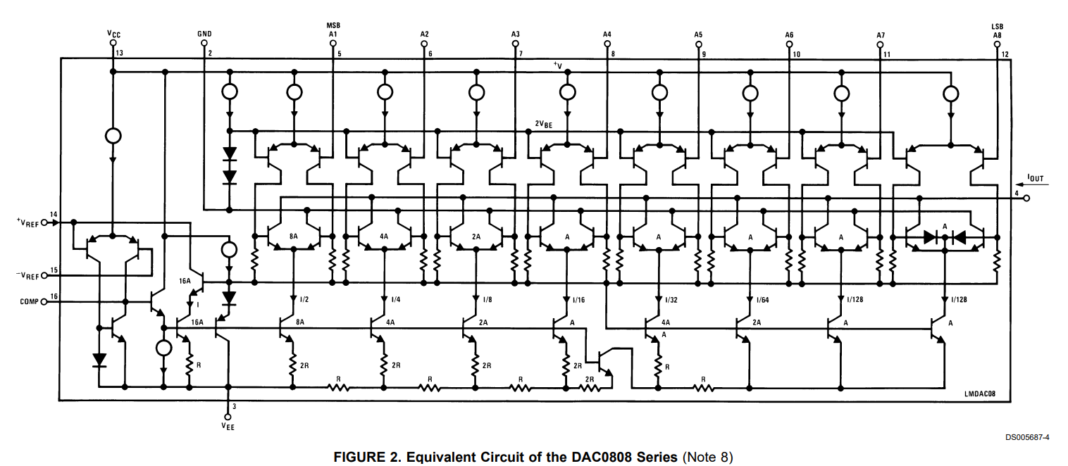
The image shows schematically how a DAC circuit looks. DAC circuits can be built with different designs – the vectrex uses a DAC based on what is called:
“Binary Ladder or R–2R Ladder D/A Converter Circuit“
(see internet for more on this)
The DAC actually outputs different analog “current” (Ampere) not analog Voltage. Further on we are going to neglect that fact… in the Vectrex block diagram you can see that right after the DAC a “Current to Voltage” converter is used – so bear again with me if I talk about “voltages”.
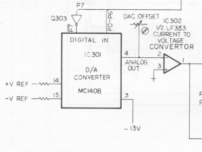
(As mentioned above, the DAC-values are unsigned, thus a generated 0 analog represents a -128 digital (signed) value etc.
In the shown Vectrex diagram you see a “DAC Offset” with this resistor (potentiomenter) you can adjust the DAC offset to align to zero.)
The DAC Datasheet describes several typical applications, one of which fits nearly perfectly how it is used in the Vectrex:
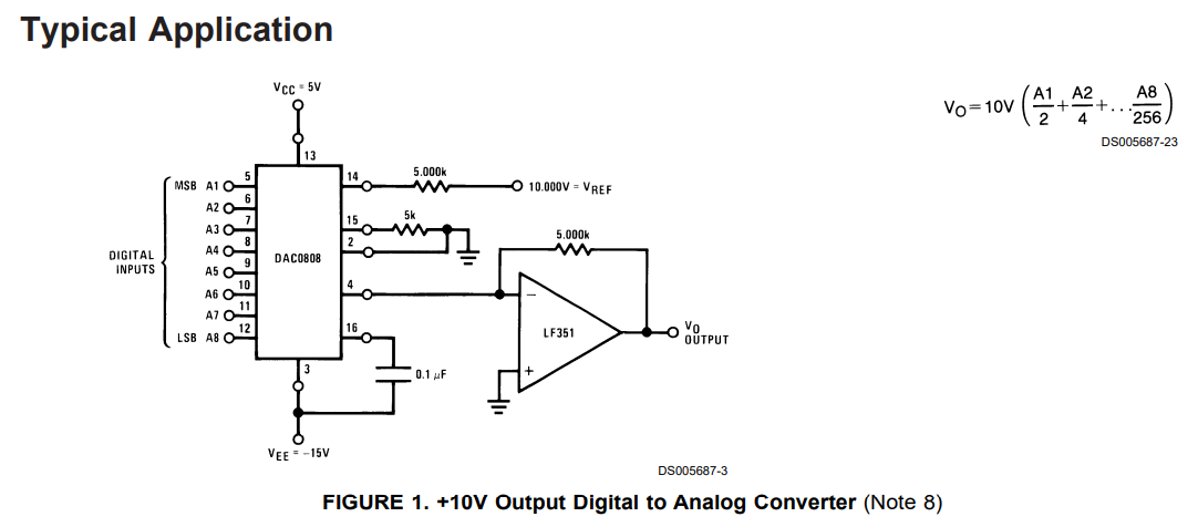
It also shows the “current to voltage” circuit.
The “ladder” produces an output voltage V0 which is generated by multiplying a reference voltage with the sum of fractions of all input bits:
V0 = VREF * ( (bit7 / 2) + (bit6 / 4) + (bit5 / 8) + (bit4 / 16) + (bit3 / 32) + (bit2 / 64) + (bit1 / 128) + (bit07 / 256) )
(bitn is 0 or 1)
Peer and I assume, that the given tolerance of +-0.19% can be applied each ladder step. This would mean, each of the summands can have an error of +-0.19%.
We also assume, that these deviations for each bit are constant (otherwise there would be a lot of shaking going on).
Ladder step 0 has an deviation d0
Ladder step 1 has an deviation d1
…
Such a deviation of +-0,19% written as a factor would be 1+- 0.0019.
When you convert a digital value to an analog value the following steps are done:
- the number for example is 64
- represent the number as binary: %0100 0000
- insert the single bits in the above equation:
V0 = VREF * ( (0/ 2)*d7 + (1 / 4)*d6 + (0 / 8)*d5 + (0 / 16)*d4 + (0 / 32)*d3 + (0 / 64)*d2 + (0 / 128)*d1 + (0 / 256)*d0 )
-> V0 = VREF * ((1 / 4)*d6 )
Value 64
One possible explanation why on my Vectrex the 64 value produces such a strong slanting is the following:
The way from left to right is done with the value of:
64 = 0b0100 0000
The way back is done with
-64 = 0b1100 0000
The difference between the two numbers is just the MSB (most significant bit). Which also produces the most significant deviation – everything else is the same – so “only” the largest possible single error is taken into account -> which in my case is large (on Peers Vectrex e.g. the 64 is not so slanted).
What about 65? (same argumentation goes also for 63)
So … why is a value of say 65 not so bad?
The way from left to right is done with the value of:
65 = 0b0100 0001
The way back is done with
-65 = 0b1011 1111
The bit difference between two numbers can hardly be bigger. The theorie, why this one is not so slanted is, that the sum of deviations (and the missing value of bit6) of bits 0-6 “compensate” the huge deviation of bit 7 (remember, the deviations can be both negative and positive).
Implementation in Vide
I implemented this in Vide with the following:
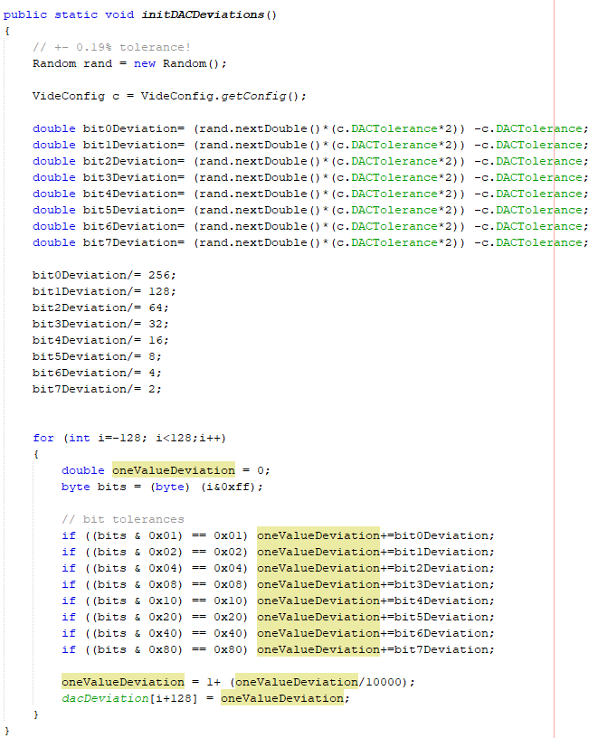
Later in the analog emulation part I use these deviations as a factor to sum up the integrator values:
            alg_curr_x += ((double)sig_dx)*(dacDeviation[sig_dx+128]);
            alg_curr_y += ((double)sig_dy)*(dacDeviation[sig_dy+128]);
IMHO this implementation is not bad per se. But there are probably other factors accounting to the overall final error.
The above implementation in Vide does not look like the actuall slanting on a vectrex.
The thing is – it seems that bits 7 and 6 dominate the slanting and bits 0-5 hardly make any difference (the produced deviation of 0.19% divided by 8 or up to 256 is just to small to be visible).
On a real vectrex the slanting changes slightly with every other number – and goes back and forth.
To account for additional other deviation aspects of the DAC – I changed the above last two lines to:
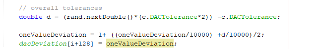
This implements an additional deviation to each DAC value. Both deviations, the bit deviation and overall deviation are equally taken into account.
But this is just some sort of hack… It looks more like a real vectrex – but this is not justified by any theory…
Comments and suggestions for improvement are welcome!
(sorry if this was double posted, my reply didn’t seem to have taken):
Fascinating stuff. I saw where it’s mentioned:
“Since the drift moves the vectorbeam in one direction – the longer the beam is not reseted – the further the drift distance. ”
Makes me wonder if, given a sentence like: “I love the DAC in my Vectrex!”, what if:
1. I send these characters to Prinet_Str(): “I love the DAC”,
2. then I reset the vector beam with Reset0Ref(),
3. then I print the remaining: “in my Vectrex!” to the right of the first string using Print_Str().
Will that possibly result in less lean? I’m going to go give it a try. I know it’s cycle intensive and inefficient to have to do this but there are many times I just want the text to look its best at all cost.
Yes less lean – for sure!