You remember the blog post: 16th of October 2022, Wobble, Jitter or Stable?
I would dearly like to do a follow up and tell you that I found out this – or that.
I can’t!
I more than once stated, that I am not one into electronics – and that has not changed. But – I am not hesitant to try out things – after all it might be that I actually learn things!
The great experiment I would like to do is:
Connect the Vectrex to another power supply and see if the Jitter/Wobble can be reduced. The thought being… the original transformer power supply has an underlying frequency of 50Hz (in Germany, 60Hz in many countries, for the sake of convenients I will talk in the following about 50Hz) – which also probably has a layer of 100Hz of ripple frequency.
For the folks not into electronics I will enter small passages which most of you will know about – but I didn’t – or at least did not take into account. The ripple frequency of 100Hz is not by coincidence double of 50Hz power frequency. The rectifier that generates DC voltage from AC voltage produces that.
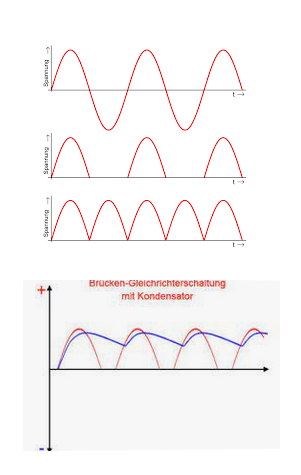
What the rectifyer basically does, is turn the SINUS wave of the power frequency and mirrors the negative wave to the positive side, see image.
One full sinus wave has two “bumps” one positive, one negative – than it starts again – in a 50Hz sinus wave each positive bump is 1/50th of a second apart.
After the rectifyer each positive bump is 1/100th of a second apart -> 100Hz (which is than called ripple frequency).
The “bumps” are also flattened out by capacitors… in the process, so the output of a rectifyer looks somewhat like:
The vectrex comes with a “classic” transformer (linear power supply) to provide its power. The thought was, that a SMPS power supply might create a more stable image.
SMPS – switched-mode power supply. About the different power supply types look at: Wikipedia
Now… the Vectrex needs different kind of voltages. The power board supplies the Vectrex with:
- +/-9V
- +/-5V
- -13V
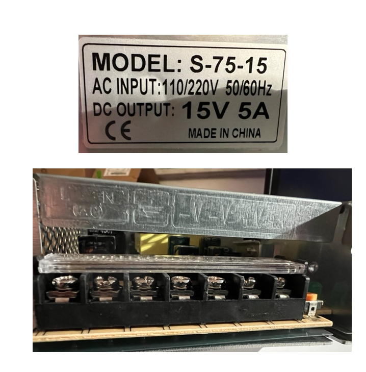
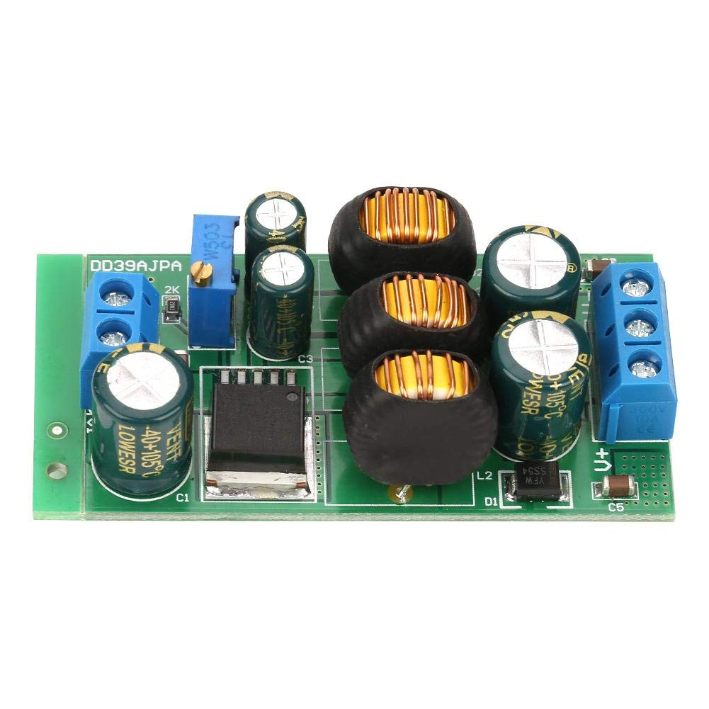
So me not being lazy – I ordered a SMPS power supply – only two weeks later it arrived: see image.
The thought was, that I could use a couple of these guys:
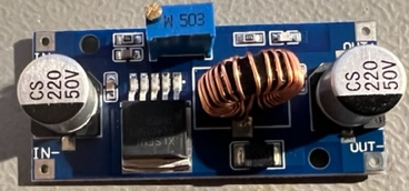
To produce the voltages required, you put power of a certain voltage in one end (in this case the “+/-” 15V from above), turn that little screw ten times anti clockwise – and measure the output voltage on the other end – stop turning when you reach your required voltage – easy!
I did that with two of these babies – one for -13V for the DAC.
And one for the input of the power board +/- 9V (Pete told me, that if I supplied the power board with 9V, than the 9V would more or less be passed thru and the +/- 5V would be “generated”).
So what I really only need is:
- +/- 9V
- – 13V
Misconceptions
That did not work. My dumb assumption was, hey – a power supply with a -V and a +V is able to supply a positive and a negative voltage. The power supply even has a ground symbol – so I would be fine.
WRONG!
The difference between the -V and +V is the voltage that is output. One of them actually being “0V” and the other one depending on the perspective either a positive or a negative voltage.
What I really needed was a “symmetric” power supply.
Because (dumb me) +/-9V actually means -9V on one side and +9V on the other side (measured against a GND) – which actually is a difference of 18V! – Which that power supply can not manage!
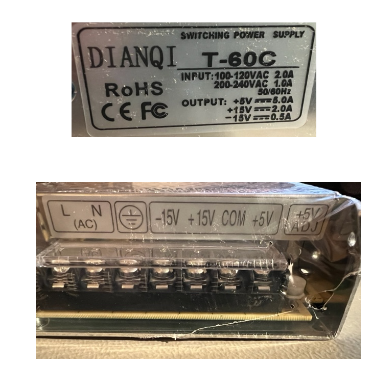
Ok… about two weeks later the next order appeared, this time: see image
Can you the see the “COM” – this more or less is GND in terms that a layman does not understand – it probably stands for “common” – I don’t know.
Getting -13V was more “difficult” than planned. All of these SMPS power supplies come with a little “adjustment” (far to the right). Being naïve I thought I could regulate the power supply down to -13V.
Nah – that would be to easy – wouldn’t it? The regulator reaches about -13.6V. While that is probably not directly destructive – I thought I’d treat my DAC with a little bit of care and provide -13V and not more – but than again -13V was not too difficult – with the regulator thing shown above this was no problem.
Getting +/-9V I thought I could use a couple of those voltage regulators connected as shown:
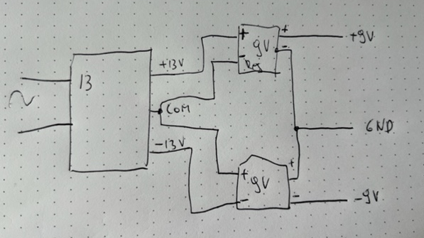
I built that and the Vectrex actually came to live! Yeah!
Nay!
The Vectrex came up really “slow” and the image was distorted. Damn, what happened?
I measured the voltages and as it turned out – the “-9V” were now “-15V” again! It appears that connecting the outgoing lines to a “common” ground nullifies the effect of the “negative” regulator.
The regulators I used are only (so to say) converting the positive voltage – putting the outgoing “pass thru” line together to a common “GND” – actually gave back the -15V of the input.
As I have found out – there are actually regulators which regulate “symmetrically” (so to say) – they more or less look like (see image) – with 3 outgoing lines.
But they are not so easy to find – and even less for a “decent” amount of current to put thru.
I ordered a couple of those – but I am not sure whether that will be worth while – the rating is pretty poor and mention, that the symmetry is actually lacking.
What I also did – I looked for a symmetrically power supply with an output voltage of +/- 9V.
I found NONE!
(looked at Ali, Mouser, Digikey and some others) Unbelievable!
I found 1 (one) SMPS power supply which outputs +/-10V. Since it also comes with an adjustment poti – I hope I can adjust it down to 9V – we will see, it will probably arrive in another two weeks or so.
(by now I have quite a collection of power supplies and regulators!)
—
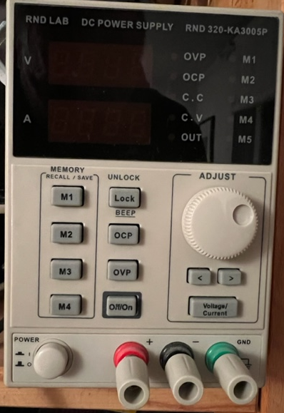
Than I had an idea – I also have an “Electronic bench power supply”:
I haven’t used it much – some time ago I thought I should have some electronic “basics” and within that thought – this was bought.
And like the layman that I am, I AGAIN thought…
Hey – three outgoing lines, plus, negative and GND – hey this could work!
Nay – I had to learn – this neither is a symmetrical power supply – and can not be used.
I either have to get a special symmetrical one again, or one with multiple seperated channels, which than can be switched together to form a symmetrical supply. But that will probably be in another life!
Now I wait for the ordered parts – and I will see how that goes.
I AM a little bit frustrated by this – both by my own ignorance – and well… everything I guess.
It’s a very long time since I looked at anything to do with power supplies and I haven’t looked at the Vectrex supply at all recently, but you might not need all this symmetrical stuff like you have it. Often you need a chunky +ve supply e.g. for 5v and the negative supply requriment is only needed in a small part of the circuit with hardly any amps. In this case, you can create a negative voltage from the positive voltage using something called a charge pump DC-DC Inverter, e.g. is a chip that does this: https://www.maximintegrated.com/en/products/power/charge-pumps/MAX1673.html
I don’t know what the -ve voltage is used for on the Vectrex PCB and this might be an out of date method, but maybe worth a look nonetheless. Also it’s perhaps worth looking at the PSU of an Atari vector game (AR2+Transformer?), comparing it with the Vectrex PSU and then looking to see what replacements are available for the Atari.
Sorry to hear/read about the failed attempts. But don’t give. Most of the times, it is all about persistence and endurance. I just experienced that myself. After 6 weeks I finally succeded in repairing my broken console. I will post about the technical details elsewhere, but let me mention here that along the way I wanted to give up several times and declare the device an organ donor for other consoles. So keep going! I have a strong feeling that, as is tradition, you will find a way to make this work!