
Again – I did pause on VB. I was – again – a bit sickly AND had a short holiday trip.
Now after the trip some Vectrex things have come up, which I probably will do in advance befor doing further VB stuff, like:
- preparing a new Vide version (most probably again based on Java 1.8), but I will probably bundle the Java version WITH vide “native packaging” which means I will provide at least three packages (Win, Mac, Linux)
- help some other people who have asked 🙂
- possibly revise Release (see Jürgens message…)
- … and communicate some interesting findings of Peer…. this is what I’ll do now!
BIOS function Draw_VLp
Many people use BIOS functions for vector drawing and that is totally fine. Especially the Draw_VLp function is quite versatile – AND quite performant. But recently Peer discovered a strange behaviour – of which we both have been aware since well over a year – but we never really researched further.
Oh well Peer (as the Professor he is by trade) – researched further now! 🙂
Look at the following sequence of images


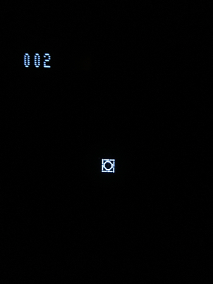


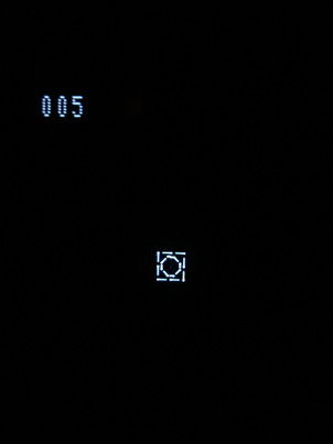

These images are all drawn from the same vectorlists, with different scale values (namely: 0, 1, 2, 3, 4, 5, 6). The “strange” occurrences you see…
- consecutivly larger gaps appearing with a higher scale and than vanishing at the seventh image
…repeat after the shown images (increasing gaps from scale 7, 8, 9, 10 ,11 12, no gap at scale 13… etc)
The corresponding very simple C test program:
1 2 3 4 5 6 7 8 9 10 11 12 13 14 15 16 17 18 19 20 21 22 23 24 25 26 27 28 29 30 31 | while(1) { DP_to_C8(); Explosion_Snd(current_explosion); Init_Music_chk(current_music); Wait_Recal(); Do_Sound(); Intensity_5F(); check_buttons(); if (button_1_1_pressed()) { ++draw_scale; } else if (button_1_2_pressed()) { --draw_scale; } position_beam_s(0, 0, 0x7F); dp_VIA_t1_cnt_lo = draw_scale; draw_vlp(square); position_beam_s(0, 0, 0x7F); dp_VIA_t1_cnt_lo = draw_scale; draw_vlp(octagon); print_unsigned_int(100, -96, draw_scale); } |
As you see nothing else but drawing the two vectorlists is done (with the corresponding changable scale).
Now – what is happening?
Lets look at the code of draw_vlp(). To compile it “together” I translated the draw_vlp to gcc compatible assembler code:
1 2 3 4 5 6 7 8 9 10 11 12 13 14 15 16 17 18 19 20 21 22 23 24 25 | void draw_vlp(void* const x) { asm("\t\n\ Draw_VLp_1: \t\n\ LDD 1,X \t\n\ STA *_dp_VIA_port_a \t\n\ STA *_dp_VIA_port_a \t\n\ CLR *_dp_VIA_port_b \t\n\ LDA ,X \t\n\ LEAX 3,X \t\n\ INC *_dp_VIA_port_b \t\n\ STB *_dp_VIA_port_a \t\n\ STA *_dp_VIA_shift_reg \t\n\ CLR *_dp_VIA_t1_cnt_hi \t\n\ LDD #0x0040 \t\n\ LF425: \t\n\ BITB *_dp_VIA_int_flags \t\n\ BEQ LF425 \t\n\ NOP \t\n\ STA *_dp_VIA_shift_reg \t\n\ LDA ,X \t\n\ BLE Draw_VLp_1 \t\n\ "); if (x==0) {}; // prevent compiler warning "unused variable" } |
Yea, yea – it looks stupid, I know -> but it works :-).
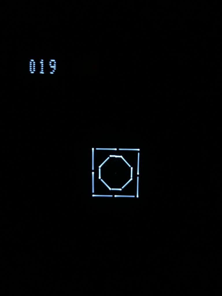
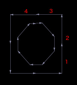
Ok – befor I go examinig and explaining the code – for better “viewing” purposes again two “larger scale” images:

Following theory of mine in respect to the above source code of draw_vlp:
- scale factor is always directly the time the vectors are drawn (the time ~RAMP is enabled and the beam is moving) so increasing the scale ALWAYS results in a larger image.
- offset of seven (changing gaps and resetting the gaps after 7 scale factors) is most probably due to the lines 16, 17, 18 – the “wait loop” which waits till the timer is finished. The BITB is an assembler instruction which takes 4 cycles, the BEQ is an instruction which takes 3 cycles. The sum of both is 7 cycles. The minimum resolution (in cycles) the wait loop can exit is 7 cycles!
- different gap sizes, if Vectrex was a perfect machine – the ~RAMP signal would be switched of exactly at the moment the timer reaches zero. Also ~BLANK would be enabled excatly at the moment the shift register is set to 0. Both of which is NOT the case. Otherwise we would see an increasingly brighter spot at the end of a vector – but we see the exact opposite – the vectors are shortened! I do not have exact values – and even Vide does as of now not emulate the above shown behaviour. But my best guess is following: The reaction time of SHIFT->~BLANK and T1->~RAMP have some (cycles) offsets. The “best” delay after which to put zero to the SHIFT register (and thus BLANK the output of the electron beam) is the one that has the most cycle delay (resulting from above “offset of seven” wait loop). Each value that the loop breaks more exact (in relation to the T1 timer reaching zero), puts the zero into the SHIFT register more early, and thus switches the beam off earlier.
Possible “solution” – bad!
Inserting a couple (4 or 5) additional NOP after line 19 will get rid of the gaps (I tested that). Thing is – if you insert for scale 5 e.g. 5 NOPs (= 10 cycles), than the above image of scale 5 will look perfectly good.
Yea!
But the image of scale 6 will have 10 additional cycles where the vector beam is switched off 10 cycles to late! Which will result in a very bright spot at the end of each vector!
Nay!
There is NO single simple solution that will look good for all scales! Not possible!
Possible “solution” – still bad, but better!
What you could do is write 7 different Draw_VLp functions, each would be programmed to fit one of the 7 different scales (and their gaps). Than you could add the perfect amount of wait cycles (NOPs) for each of them and always have nice images.
Possible “solution” – good, but restricting!
Only use scale values which fit the original Draw_VLp function from the BIOS! That would be scales: 0, 6, 13, 20, 27, 34, 41, … etc
White starts!
If you look again at image “19” (scale 19 I mean), you will notice, that each of the vectors starts with a bright spot. This is due to line 13 and line 14.
The ~BLANK is switched off before the ~RAMP is switched on. Strangely enough, here the analog hardware of the Vectrex seems to react immediatly :-).
More explanation. In line 9 the register A is loaded with the next “pattern” (that is actually more a “mode” than a pattern) that is to be used. For lines this is “$ff” for moves this is “0” and for end of list the value is one of “$01 – $7f” (a positive value that is not 0). The value $ff here is the interesting one. In binary that is %11111111. That value is put into the SHIFT register. And after putting it into the SHIFT register these “1”s will be shifted one to the left, and the most significant bit is put to ~BLANK. Every two cycles one such SHIFT will occur so that after 16 cycles all 8 values have been passed to the ~BLANK (and thus “lightened” the screen for 16 cycles. Since VIA is “broken” it will shift the last (above least significant bit) value AGAIN to the ~BLANK (thus a complete shift will take 18 cycles).
And since VIA doesn’t know what else todo – the last shifted value will STAY, so after the above shifting ~BLANK will stay disabled (a ONE will disable blank and thus “unblank” -> brighten … etc).
Ok in short – the light is switched on after in line 13.
After line 14 the electron is moving. Putting a value into the “hi” counter of T1 starts the timer (oops, that is an oversimplification, what happens if you write into T1 hi counter is:
a) t1 lo latch is loaded to t1 lo counter
b) t1 hi counter is loaded to t1 hi latch
c) counter starts
d) t1 interrupt flag is cleared)
But anyway – as soon as the T1 timer starts (and the rest of VIA is set up correctly) bit 7 of VIA_Port_B is set to zero, which is connected to the “~RAMP”, setting it to zero enables ~RAMP, which means the electron beam starts to move. PB7 (~RAMP) will be set to one automatically when the timer reaches zero.
Ok also in short – as soon as a value is put into T1 hi, the vector beam starts moving till the timer reaches zero.
Both in short:
The electron beams brightness is switched on befor it starts to move (4 cycles – not taking into account whatever internal other “delays” there might be). Therefor there is a bright sport in the beginning of each vector!
Bright spot solution?
Ok, while we are talking about it – there could be a solution for the bright spot (and it has been done so by other clever programmers). The above mentioned $ff that is put into the SHIFT register.
THAT could be changed to something which disables ~BLANK later.
The $ff -> %11111111 could e.g. be exchanged with a %00001111, which would result in a 8 cycle delay before ~BLANK is disabled and thus probably eliminate the bright spot.
But beware -> it would not be the Draw_VLp anymore – since the pattern value is read from the vectorlist. You must either do additional tests for negative value ($ff) and than exchange the $ff with above $0f or…
I’m sure if you want to, you can figure out clever ways :-)…
Ok…
Enough written for today.
Great, many thanks for the detailed analysis and for writing this up!
Personally, when I am following my retro C approach (do all the game logic in C and exclusively use the original BIOS functions for all hardware access), I was particularly annoyed by the “gaps”. I found that, for me, the simple solution of restricting oneself to scale factors 0, 6, 13, 20, 27, … works best. By slight adjustment of the lengths of the vectors I can usually still get the desired size of the objects on screen.
I do not really mind the “bright dots” at the connection points of the vectors that much, because I have just gotten so used to them during my childhood. For me it is just the way Vectrex games always looked. Same with the buzz. I only had a buzz Vectrex as a child, and I simply took the buzz for granted. Whenever I switch on my no buzz machine today, I get a bit jump scared: No noise! Oh, is the device broken?
The thing that really surprised me was that Draw_Vlp-ing the same vector list with scale factors 0 – 5 always takes exactly the same number of cycles. Scale factors 6 to 12: same number of cycles, 13 – 19: same number of cycles, and so on. I had naively assumed that performance of Draw_Vlp is fully linear in the value of the scale factor, but never fully checked. Now noticing the above was what got me started to investigate in more detail, and then I stumbled across the “gaps” again, which Malban an me had run into already some time ago. At that past point, Malban came up with an own and slightly modified implementation of Draw_Vlp, and I thankfully used it and did not investigate any further (though it always bothered me a bit not to use the original BIOS).
Cheers,
Peer
It’s funny, I just experienced this with my latest game I’m coding… the Bandidos “sprite” I was experimenting with different scales to see how it affected performance and at certain scales I had gaps but not at others.
Pingback: 15th of March 2022 – Mystery continued! – Vectrex Blog